3D Wire Forming: Equipment Selection for Complex Parts
Jump to section
Making complex 3D wire parts requires specialized equipment that can handle multiple bends, angles, and precise dimensions in a single automated process. The right 3D wire forming machine depends on wire diameter, part complexity, production volume, and required precision—with options ranging from single-head CNC benders for simpler geometries to multi-axis systems that handle intricate shapes without secondary operations. Companies that choose the wrong equipment face higher costs, slower production, and quality problems.
Wire forming equipment has changed how manufacturers make complex parts. Modern CNC wire forming machines use computer control and servo motors to bend wire from 0.010 inches to 0.47 inches in diameter. These machines eliminate manual bending and reduce the need for welding or assembly.
This guide explains what makes a wire part complex, compares different types of 3D wire forming equipment, and outlines the factors that determine which machine fits specific production needs.
3D wire forming creates parts that bend in multiple directions and planes, unlike 2D parts that remain flat. Complexity increases with the number of bends, tight radii, and material properties.
2D wire bending produces flat parts with all bends in a single plane. Examples include simple hooks, clips, and brackets that can lie flat on a surface.
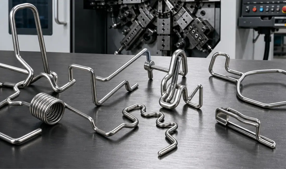
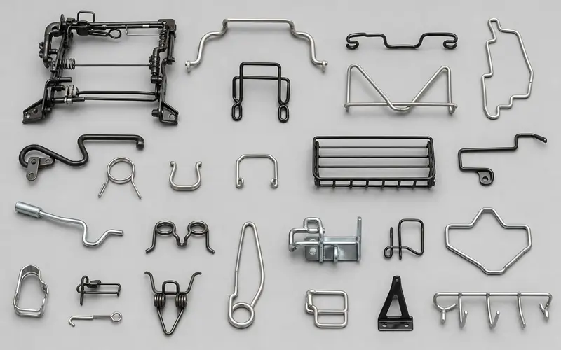
3D wire forming bends wire in multiple planes to create parts with depth and height. A 2D part requires movement along an X and Y axis. A 3D part adds a Z axis, allowing the wire to move up, down, and rotate in space. This capability produces seat frames, hangers, linkages, and medical device components.
The equipment differs significantly. 2D machines use 2 to 4 axes of movement. 3D machines require 5 to 24 axes to control wire position, rotation, and bending direction. More axes mean greater flexibility but also higher machine cost and programming complexity.
CNC 3D wire forming machines use computer programming to control these multiple axes simultaneously. The machine feeds wire, rotates it to the correct angle, and bends it in the specified direction.
Multiple bends in different planes create the primary source of complexity. A part with 15 bends across three planes requires precise coordination of all machine axes.
Tight bend radii challenge the equipment and material. Bends closer than 2 times the wire diameter risk cracking or deforming the material. Materials with high tensile strength require more force and specialized tooling.
Wire diameter affects production difficulty. Parts using wire from 0.010 inches to 0.120 inches demand different machine capabilities. Thicker wire needs more powerful servo motors and stronger bending heads.
Material type adds complexity. Stainless steel and titanium resist bending more than copper or aluminum. Coated wires require careful handling to prevent surface damage.
Geometric features that increase complexity:
Complex parts often combine several of these features. A medical guidewire might use thin wire with multiple tight radii and require biocompatible material. An automotive seat frame might have 20+ bends across multiple planes with strict safety tolerances.
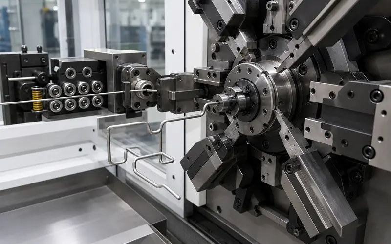
Three primary machine types handle complex 3D wire forming: CNC 3D wire bending machines for multi-axis precision work, multi-axis CNC wire formers that combine bending with coiling, and cam-driven multi-slide machines for high-volume production. Each technology offers distinct capabilities for wire diameter ranges, production speeds, and part complexity levels.
A CNC 3D wire bending machine uses computer-controlled servo motors to form wire in multiple planes simultaneously. These machines handle wire from 0.4mm to 16mm diameter with positioning accuracy of ±0.1mm.
The machine feeds wire from a coil through a straightening unit. Multiple bending heads move independently on different axes to create complex three-dimensional shapes. Most modern systems use 7 to 12 axes of motion.
Single-head configurations work best for parts under 500mm in length. Double-headed machines process longer components or produce two parts simultaneously. The bending heads rotate 360 degrees and can create bends in any direction without repositioning the wire.
Feed rates reach 5,000mm per minute on high-end models. Bending speeds hit 5,000 degrees per minute. These machines store thousands of part programs and switch between different products without manual tool changes.
All-electric systems dominate current production. They consume less energy than hydraulic machines and deliver more consistent results across production runs.
Multi-axis CNC wire formers combine wire bending capabilities with spring coiling functions in a single machine. These systems handle both compression springs and complex formed wire parts from 0.3mm to 20mm diameter.
The machines use 4 to 8 servo-controlled axes that operate independently or together. Wire feeding, rotation, bending, and coiling happen at the same time during the forming cycle. This parallel operation cuts cycle times compared to sequential bending machines.
Tool changers hold multiple forming tools. The machine automatically selects the correct tool based on the programmed part geometry. Manufacturers produce torsion springs, extension springs, wire forms, and clips without stopping for manual setup changes.
Production speeds vary by wire diameter and part complexity. Machines form simple springs at rates exceeding 200 parts per minute. Complex 3D wire components take 10-30 seconds per part.
These formers are common in automotive, medical device, and electronics manufacturing where parts combine spring characteristics with specific geometric features.
Cam-driven multi-slide machines use mechanical cams to control multiple forming slides that shape wire at the same time. These machines produce parts at speeds up to 400 pieces per minute for simple geometries.
Each forming operation requires a custom cam machined to specific profiles. The cams drive slides that bend, cut, and form wire as it feeds through the machine. Four to eight slides work together in coordinated sequences.
Setup changes require physical cam replacement and mechanical adjustment. Changeover time ranges from 2 to 8 hours depending on part complexity. This makes cam machines suitable for high-volume production runs of 100,000+ parts.
Wire diameter capacity spans 0.5mm to 6mm on most models. Larger specialty machines handle up to 10mm wire. The mechanical nature of cam systems limits precision to ±0.2mm, which suffices for commercial wire forms but falls short of aerospace or medical requirements.
Cost per part drops significantly at high volumes. The machines run continuously with minimal operator intervention once properly set up.
Equipment selection depends on the part’s geometric complexity, the wire’s physical properties, and how many parts need to be produced. These three factors directly determine machine capability requirements, tooling needs, and cost-effectiveness.
Parts with bends in multiple planes require 3D machines with at least 3 axes of movement. A 2D machine only bends wire in a single flat plane. A 3D machine adds vertical movement and rotation to create spatial forms.
Typical axis configurations include:
Single-head machines process one bend at a time. Double-head machines perform two bending operations simultaneously, which reduces cycle time for parts with bends at both ends. Parts requiring twists, loops, or multiple bend angles in different directions demand machines with additional rotational axes.
The number of re-clamps needed on simpler machines also affects the decision. A 3D machine eliminates most fixture changes that a 2D machine would require for the same spatial part.
Wire diameter determines the bending force required and limits which machines can handle the job. Most 3D wire bending machines process wire diameters within a 3-4× range. A machine rated for 2-8 mm cannot effectively bend 12 mm wire.
Material hardness affects tooling wear and bending accuracy. Stainless steel requires more force than mild steel. Spring steel demands precise overbend compensation because it springs back after forming. Aluminum bends easily but scratches without proper tooling surfaces.
Cross-section shapes include:
Machines designed for round wire may not accommodate flat bars without specialized tool holders. The double tool holder turret option allows processing of different cross-sections on the same machine without manual tool changes.
High-volume production justifies machines with faster cycle times and automated wire feeding from coil. Low-volume custom work benefits from machines with quick programming and tool changeover capabilities.
Machines that load from coil reduce material handling for runs exceeding 1,000 parts. Bar-fed machines work better for short runs or parts requiring pre-cut wire lengths. CNC control systems with intuitive programming reduce setup time between different part numbers.
Production runs requiring frequent changeovers need machines with stored programs and quick-change tooling. A facility producing 50 different wire forms per month requires different capabilities than one making millions of identical parts. Automated tool changers cut setup time from hours to minutes between jobs.
Equipment selection depends on production volume, part complexity, and required precision. CNC machines offer flexibility for prototypes and varied production runs, while cam-driven systems excel at high-volume runs of identical parts.
CNC wire forming machines use computer programs to control all bending operations. These machines allow operators to change part designs without replacing physical tooling. Setup times range from 15 minutes to 2 hours depending on part complexity.
The primary advantage is flexibility. A single CNC machine can produce many different part designs in one production run. Programming changes cost only labor time.
CNC systems work well for wire diameters from 0.010 inches to 0.47 inches. Modern 5-axis to 24-axis configurations handle complex 3D geometries that require multiple bend angles and planes.
The disadvantage is cycle time. CNC machines typically produce 10 to 30 parts per minute for moderately complex forms.
Cam-driven machines use mechanical cams and stops to control bending operations. Each part design requires dedicated tooling. Tooling costs range from $500 to $5,000 per part design.
These machines produce 60 to 200 parts per minute once set up. The speed advantage matters when producing thousands of identical parts. Cam-driven systems maintain tighter tolerances across high-volume runs because mechanical stops eliminate programming drift.
The main disadvantage is inflexibility. Design changes require new tooling and setup times of 2 to 8 hours.
Choose CNC equipment when producing fewer than 50,000 parts per year of a single design. The lower tooling costs offset slower cycle times. CNC systems are the only practical option when part designs change frequently or when producing prototypes.
Companies running medical device components or custom orders benefit from CNC flexibility. A manufacturer producing many different bracket designs at moderate volumes saves significant tooling costs with CNC equipment.
Choose cam-driven machines when annual production exceeds 100,000 parts of identical designs. The cycle time advantage generates payback within 6 to 18 months at these volumes. High-speed cam systems justify their tooling investment through reduced labor costs per part.
Wire diameter also influences the decision. Parts using wire thicker than 0.25 inches often require cam-driven machines because they deliver the mechanical force needed for consistent bends.
Mixed production environments need both machine types. Many shops use CNC equipment for initial production runs and prototypes, then switch to cam-driven systems once a part design stabilizes at high volume.
Integrated secondary operations eliminate part handling between stations. Each transfer between machines adds 3 to 10 seconds of cycle time and increases the risk of part damage.
Critical secondary operations to consider:
Machines with integrated cutting reduce cycle time by 5 to 8 seconds per part compared to separate cutting operations. The TBE Multibend series integrates multiple operations in single-head or twin-head configurations.
Support tables stabilize parts during forming. HTC machines rotate wire within the tooling, and support tables prevent deflection on parts longer than 6 inches. This helps maintain dimensional accuracy across the part length.
Part collectors automate downstream handling. Automated collection systems prevent surface damage and enable lights-out manufacturing for long production runs.
Servo resolution determines positioning accuracy to within 0.001 inches on high-end systems. Machines with 0.01-degree rotational accuracy produce consistent bends.
The number of servo axes affects geometric complexity more than precision. A 5-axis machine handles basic 3D shapes, while a 12-axis machine creates complex geometries with multiple bends in different planes.
Tooling precision is important because worn or misaligned bending heads introduce errors. Buyers should check tool holder tolerances and replacement intervals during evaluation.
Wire straightening quality affects dimensional consistency before the first bend. Multi-roller straighteners with 5 or more contact points remove coil memory better than 3-roller systems.
Feed control accuracy determines where each bend occurs along the wire. Servo-driven feeds maintain 0.5 mm repeatability. Stepper motors may drift by 2-3 mm over long runs.
Most complex wire parts use steel, stainless steel, aluminum, or copper alloys in diameters from 0.010 to 0.47 inches. Spring steel and stainless grades require about 30 percent more bending force than mild steel at the same diameter.
Machines rated for 0.47-inch maximum diameter handle most automotive and furniture applications. Medical device components typically need 0.010 to 0.120-inch capacity with tighter tolerances.
Material hardness ratings determine machine torque requirements. A machine bending 0.25-inch diameter wire at 200 HB hardness needs different tooling than one processing 300 HB material.
Multi-material capability requires adjustable feed rates and bend speeds. Steel processes at different speeds than aluminum to prevent work hardening or surface damage.
Purchase price represents 40 to 60 percent of five-year ownership costs for CNC wire forming equipment. Tooling, maintenance, and labor make up the remainder.
Tooling costs range from $2,000 to $15,000 annually, depending on production volume and part complexity. Quick-change tool systems can reduce setup time from 2 hours to 20 minutes between jobs.
Maintenance intervals vary by manufacturer but typically require 8 to 16 hours of service per 2,000 operating hours. Servo systems require less maintenance than pneumatic or hydraulic systems.
Operator training requires 40 to 80 hours for basic programming skills on CNC systems. Machines with 3D programming interfaces can reduce training time by 30 percent compared to text-based systems.
Setup time per new part ranges from 30 minutes to 4 hours, depending on geometric complexity and programming method. Simulation software helps reduce physical test runs and material waste during setup.
Energy consumption adds $500 to $2,000 annually for machines running single shifts. Double-head machines processing two parts at once use 40 percent less energy per part than single-head machines.