Automatic Outer Casing Cutting Machine
Servo-driven automatic cutting for control cable outer casings — accurate, fast, burr-free.
View machineMECHANICAL CONTROL-CABLE CASINGS
Form the casing. Add the cover. Prepare the ends.
BOBO supplies machines for winding flexible control-cable casings, applying PVC/PE outer coatings and cutting casing to length. The range includes double-wire winding and a separate cut-and-chamfer model for prepared coated casing. Select the stages needed for your brake, clutch or throttle cable housing.
Casing winding with an optional inner liner
PVC/PE extrusion coating of prepared casing
Cut-to-length and cut-and-chamfer routes
Outer Casing Machine
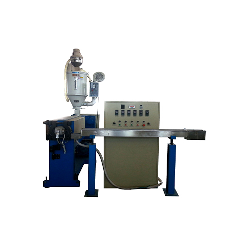
PVC/PE coating equipment for prepared control-cable casing
DEFINE THE CASING LAYERS
Wound structure, inner liner, outer coating and finished ends.
FIND YOUR MACHINE
Compare the FX-I and FX-2 winding models with the FX-3D double-wire machine for your casing construction and diameter. Use the coating line to add a plastic outer layer. For prepared casing, choose the QG cutting route or the dedicated cutting-and-chamfering machine when the end drawing requires inner and outer edge work.
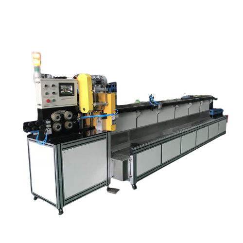
Servo-driven automatic cutting for control cable outer casings — accurate, fast, burr-free.
View machine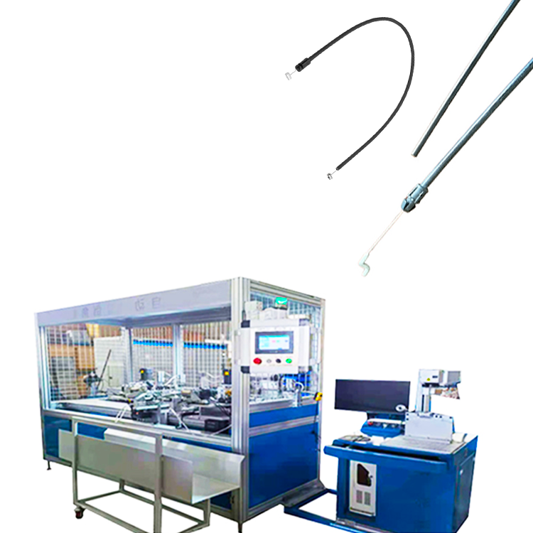
Automated cutting and chamfering of control cable outer casings in one continuous operation.
View machine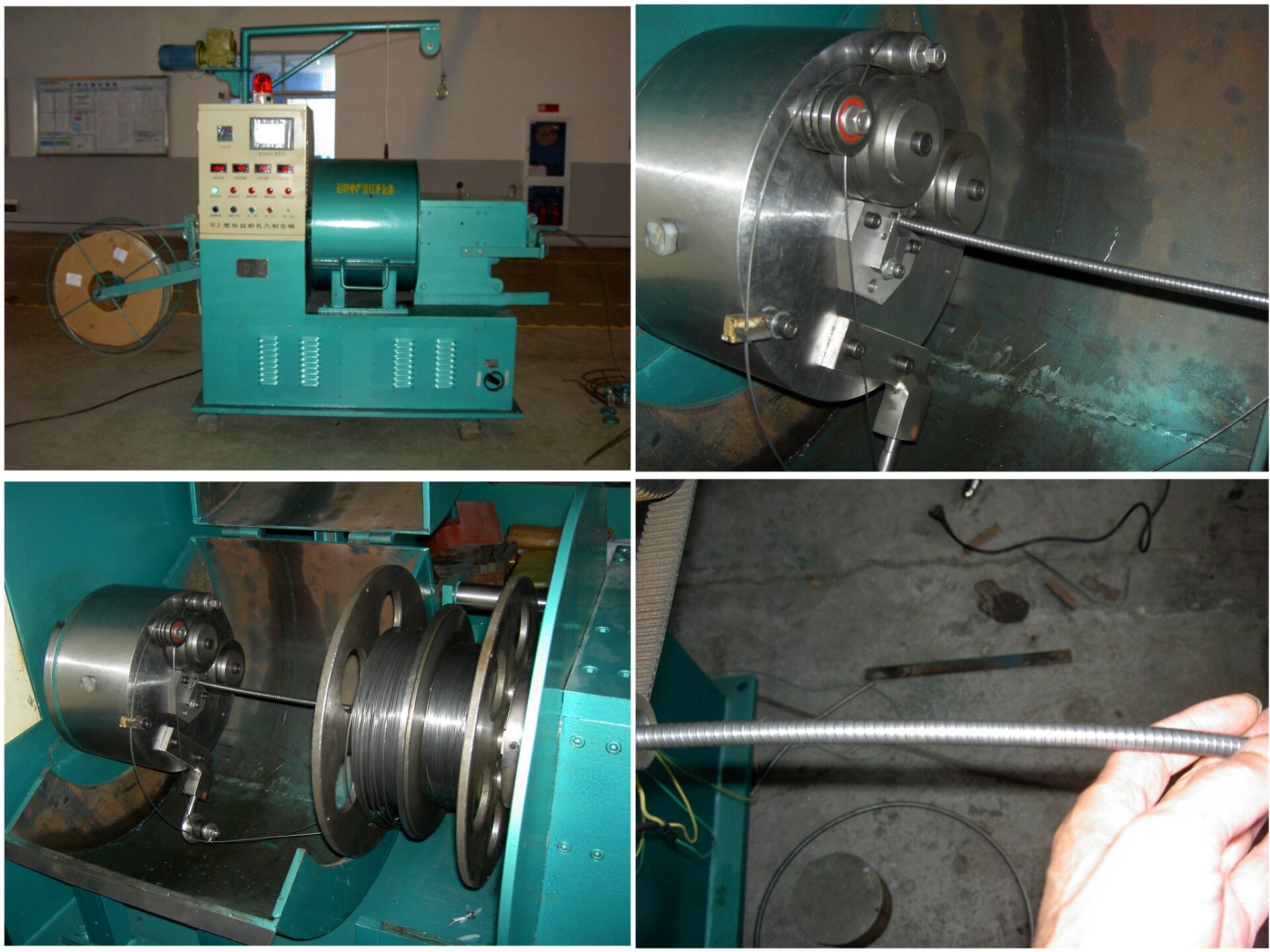
Continuous double-wire winding for high-output flexible control cable casing production.
View machine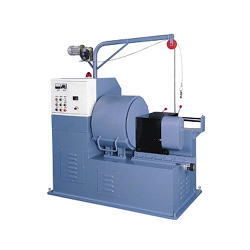
Continuous flexible outer casing production for brake, clutch, and throttle control cables.
View machineContinuous PVC/PE extrusion coating for outer casing conduit in one automated line.
View machineWorking ranges are model-specific. Confirm material, product dimensions and the required operation against the selected machine.
PARTS & APPLICATIONS
The outer casing guides the moving cable within a mechanical control assembly. Its wound structure, inner liner, outer cover and finished ends need to match the cable design and the next assembly operation.
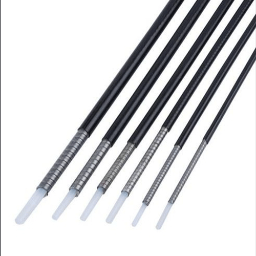
01
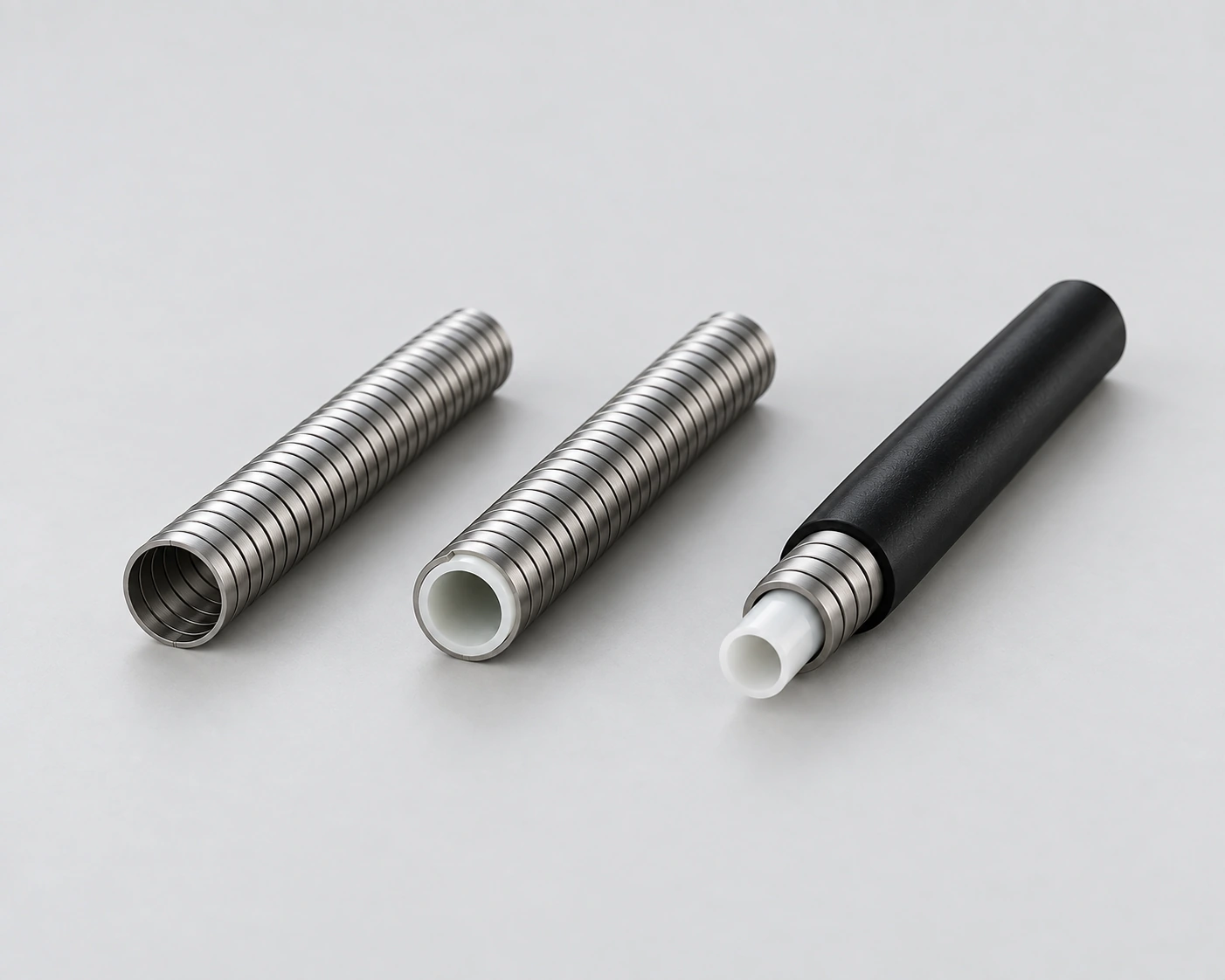
These examples show a plastic inner liner, wound metal casing and an outer cover. Winding builds the metal structure around a prepared liner; coating adds the outer plastic layer in a separate stage.
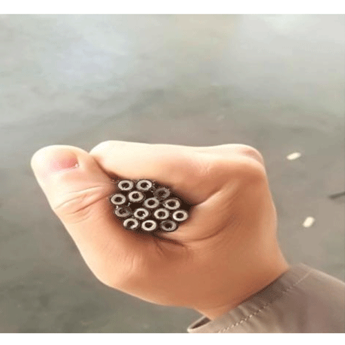
02
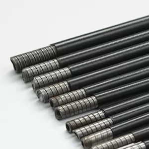
Prepared casing is divided into lengths for brake, clutch and throttle cable assemblies. Select the cutting setup around the casing diameter, length and required condition of the cut end.
03
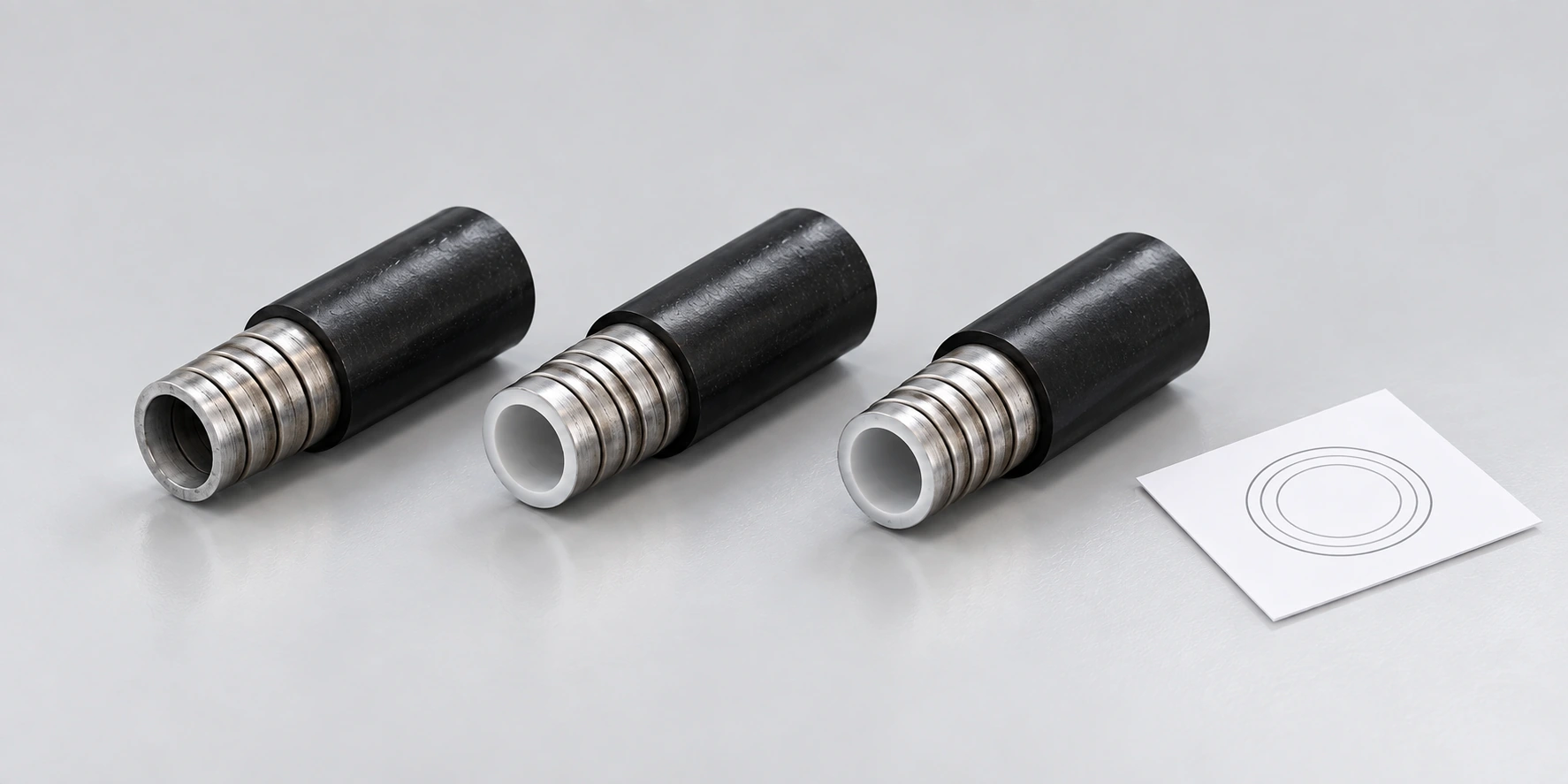
The cut-and-chamfer route adds inner-hole and outer-edge preparation to coated casing. Use the end drawing to define the chamfer and the fit needed for subsequent fittings or cable insertion.
SELECTION GUIDE
Begin with a casing section drawing: wire construction, metal casing dimensions, any inner plastic liner and the outer coating. Then define the finished length and end condition. A winding diameter, coated outside diameter and cutting diameter describe different stages of the same part.
01
Specify the wire profile and winding arrangement, metal casing dimensions, inner liner and outer cover. Identify whether you start with wire or with an already formed or coated casing.
02
Select winding for the metal structure, extrusion coating for the outer cover, and cutting for finished lengths. Add chamfering only where the end drawing calls for inner-hole or outer-edge preparation.
03
Review reel or coil dimensions, payoff direction, forming speed, cooling and collection. Plan size changes and dimensional checks across the stages that will be linked.
Plan the transfer between winding, coating and end preparation. Reel capacity, feed direction, processing speed and cooling requirements determine whether stages should be linked or operated separately.
YOUR FINISHED PART
Include the material, dimensions and acceptance requirements.
From technical review and testing to delivery and after-sales.
BOBO can review the casing structure and incoming materials to define winding tooling, coating dies and cutting or chamfering requirements. Agree trials on the intended wire, liner and prepared casing, with checks for layer dimensions, cut length and end condition. Include reel handling, utilities, changeover and maintenance in the delivery scope.
Casing section and material review
Winding, coating and end-tooling selection
Trial lengths and dimensional checks
Reel handling, utilities and changeover planning
BEFORE YOU CHOOSE
Separate the casing layers and end operations to avoid specifying the wrong production stage.
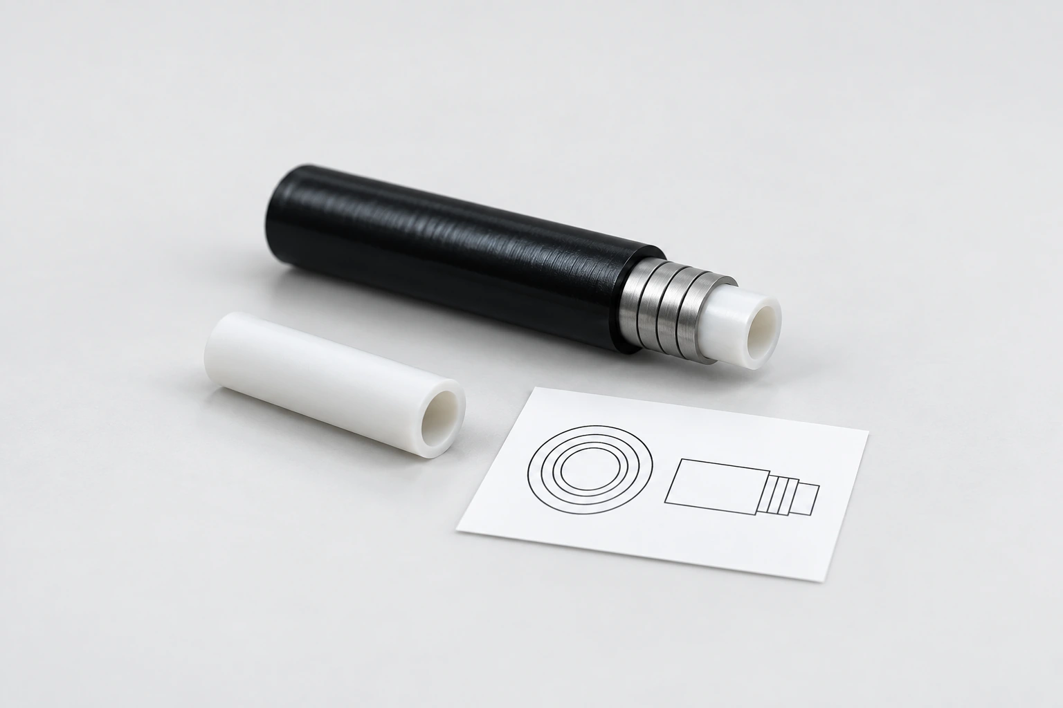
The winding machines can feed an optional pre-made plastic inner hose with the wire. A separate extrusion process produces that liner. BOBO’s PVC/PE coating line applies an outer plastic layer to prepared casing, which is a different task.
Use the casing construction and finished dimensions first. The FX-3D has a double-wire arrangement with separate bobbin, differential and braking mechanisms, while the FX-I and FX-2 serve their own casing specifications. Wire count alone does not establish the casing’s compression performance or the best production rate.
No. The QG machine uses a grinding wheel to cut the casing to length. A separate cutting-and-chamfering model processes the inner hole and outer edge. Specify the end geometry and acceptance checks when chamfers are required for the next assembly step.
They cover different stages and product ranges. A combined arrangement needs compatible casing dimensions, feed speeds, cooling, reel handling and controls. Define the required stages and their transfer interfaces as part of the equipment proposal.
START WITH A DRAWING OR SAMPLE
Include wire material and profile, winding construction, metal casing inside and outside diameters, liner specification, coating material and thickness, finished length and end requirements. Add the target output, incoming reel or coil sizes and the stages you already perform.
For coating, include prepared casing samples and the proposed plastic grade. For cutting or chamfering, include coated casing samples and the required length and end tolerances.
Outer Casing Machine / BOBO MACHINE