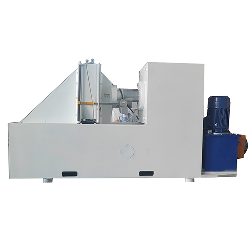
Sectional Helical Spiral Auger Blade Press Rolling Machine SFR-160
160-ton spiral blade press forming blades up to 2000mm diameter and 35mm thick.
View machineSECTIONAL SCREW FLIGHT FORMING
Form individual helical flights around the geometry of your screw or auger.
BOBO’s sectional-flight machines form separate helical pieces for screw conveyors, mixing equipment and drilling augers. Select the machine and forming tools around the material, inner and outer diameters, pitch and thickness, with particular attention to how each flight will fit and join in the finished assembly.
Individual screw and auger flight sections
Carbon-steel and stainless-steel options
Left- and right-hand forming arrangements
Sectional Spiral Blades Forming Machine
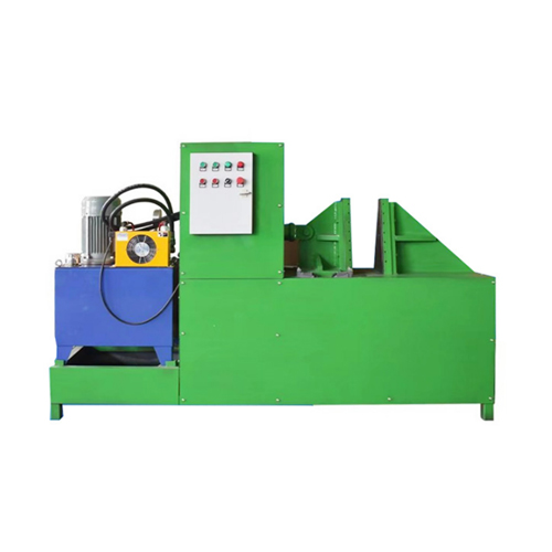
BOBO SFR-200 sectional spiral-flight forming equipment
DEFINE THE COMPLETE FLIGHT
Inner and outer diameter, pitch, thickness and handedness.
FIND YOUR MACHINE
The SFR-30, SFR-100, SFR-160 and SFR-200 occupy different working ranges. Compare the material and full combination of flight dimensions, then review the forming tools, positioning adjustments and workpiece handling. Maximum thickness, diameter and pitch are not independent settings that can always be combined.
160-ton spiral blade press forming blades up to 2000mm diameter and 35mm thick.
View machineCold-roll spiral blades from 2–30mm thick steel in any pitch up to 7000mm.
View machine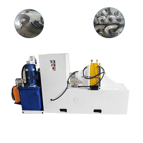
Cold-roll precision spiral blades from 2–16mm stock in minutes, not hours.
View machine
Form spiral blades from 30mm to 1000mm diameter — no mold changes required.
View machineWorking ranges are model-specific. Confirm material, product dimensions and the required operation against the selected machine.
PARTS & APPLICATIONS
Sectional flights provide separate helical pieces that can be fitted to a shaft or joined into the required screw construction. Their inner-edge fit, pitch and joining ends are central to the next fabrication step.
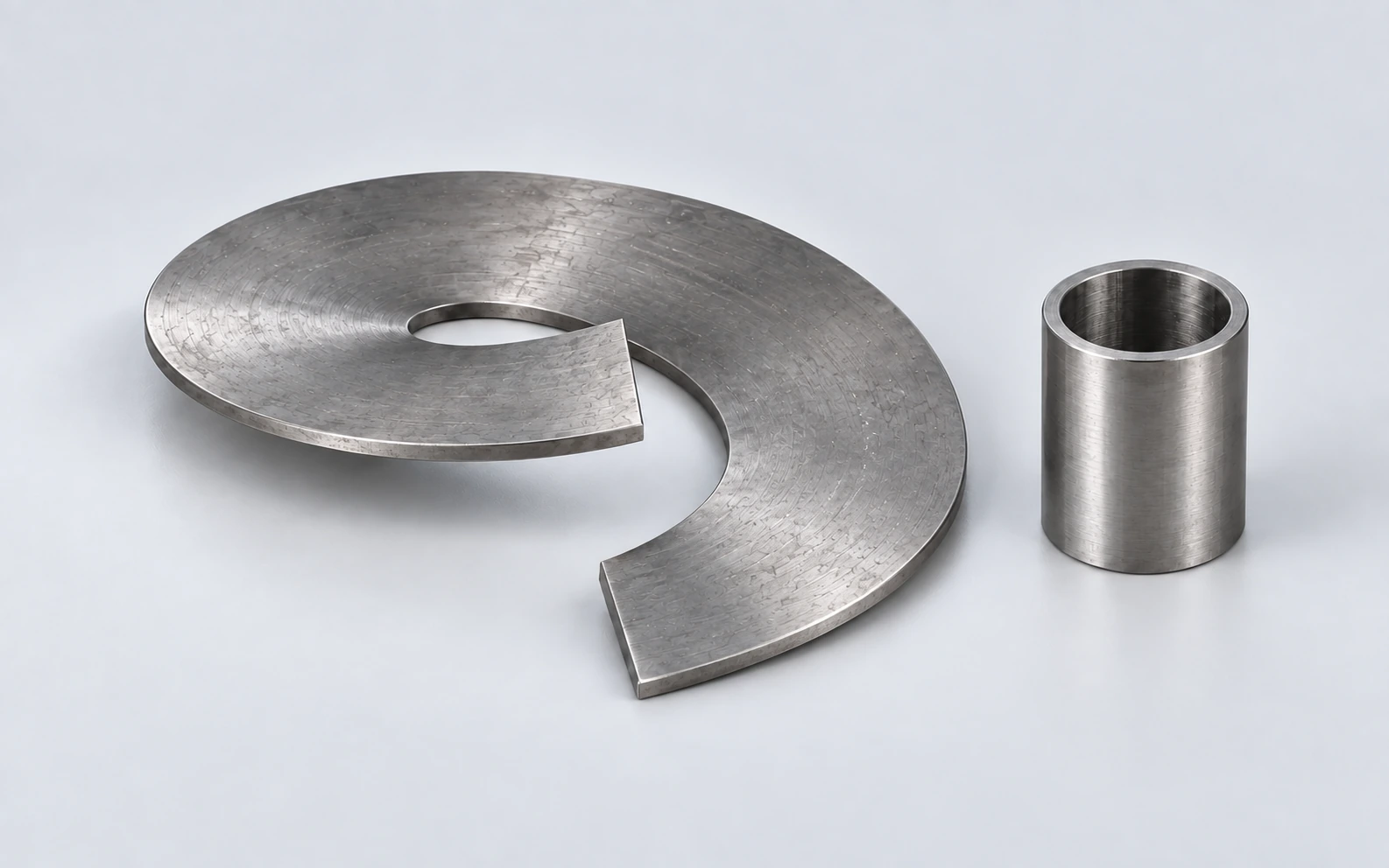
01
Form individual flight pieces to fit the specified shaft or pipe. Check the inner profile and pitch before positioning and welding the pieces into a conveyor screw.
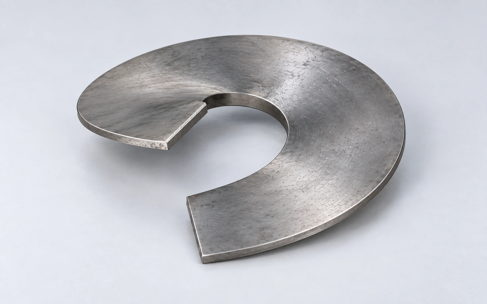
02
Produce flight sections for auger fabrication around the required diameter, pitch and material. Cutting edges, wear parts and the final auger assembly are separate details to specify.
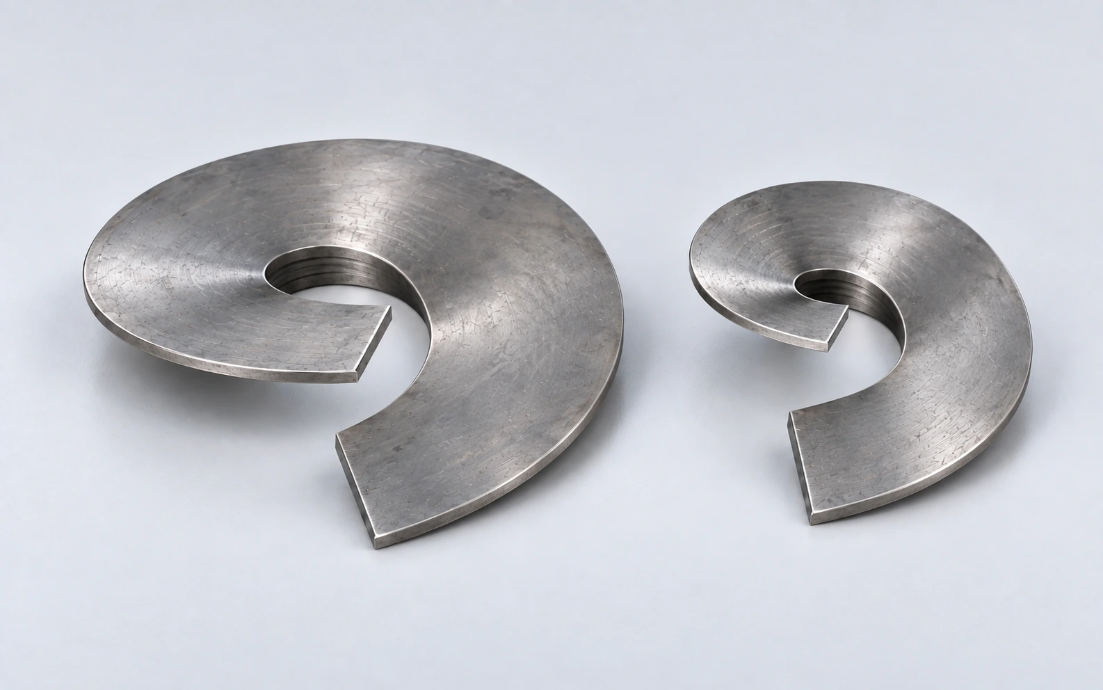
03
Form helical pieces for mixing or material-handling equipment. Define the flight drawing and joining arrangement so the formed parts fit the intended screw construction.
SELECTION GUIDE
Thickness alone does not define the forming task. Material strength, flight width, pitch and the relationship between inner and outer diameter all affect the workpiece and tooling arrangement.
01
Provide inner and outer diameters, pitch, thickness, handedness and material grade. Include the flat-blank drawing or ask for its preparation to be reviewed alongside the finished-flight drawing.
02
Review the required part family against the chosen model’s forming range and tool arrangement. Include left- and right-hand work, tool changes and practical support for the blank during forming.
03
Use trial flights to check dimensions, pitch, joining ends and shaft fit where applicable. Estimate output with blank handling and the full forming sequence, then define the handoff to welding or assembly.
Plan blank cutting, flight forming and later welding as distinct operations. A forming trial should check the geometry needed for assembly, including inner-edge fit and the alignment of adjoining ends.
YOUR FINISHED PART
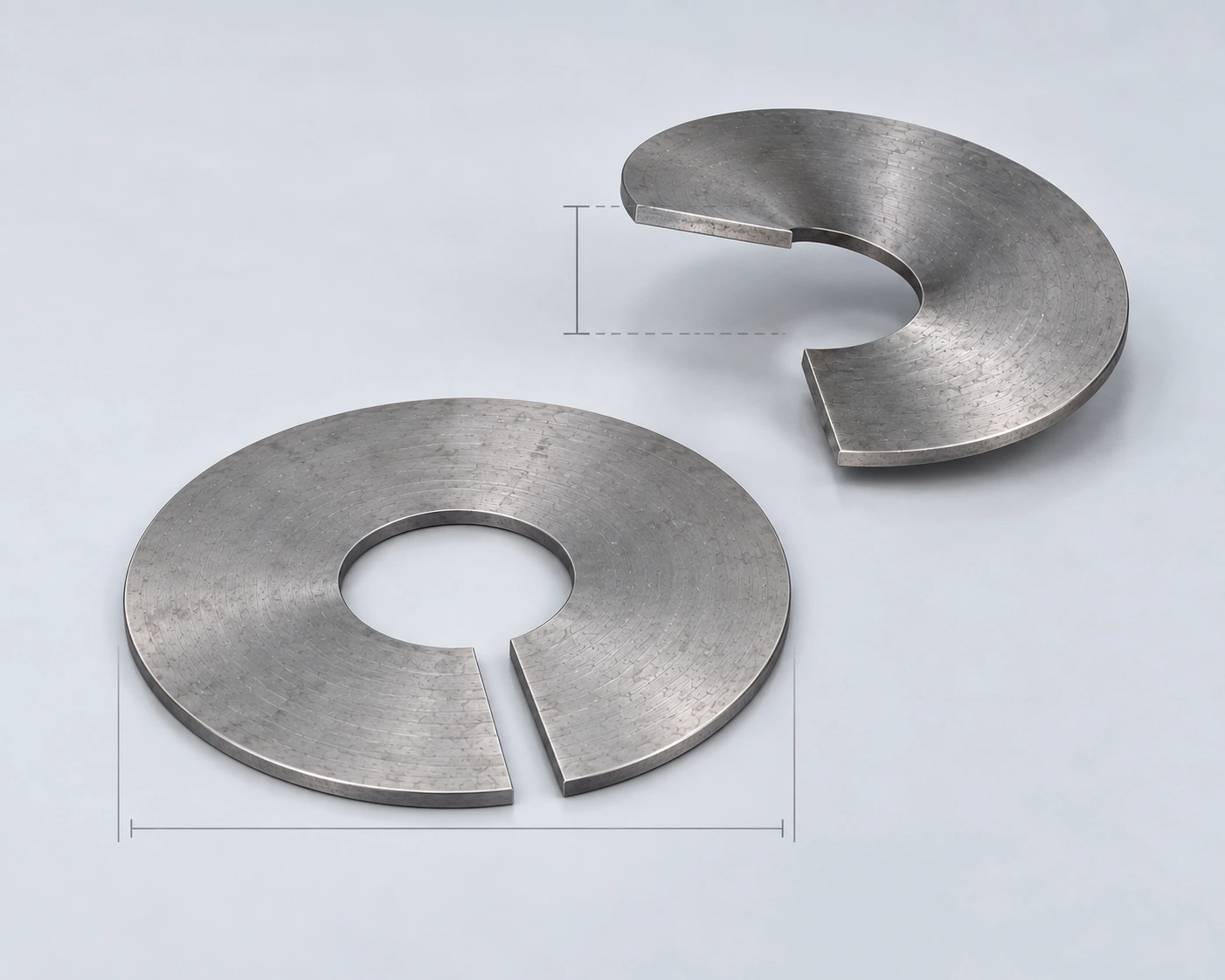
Include the material, dimensions and acceptance requirements.
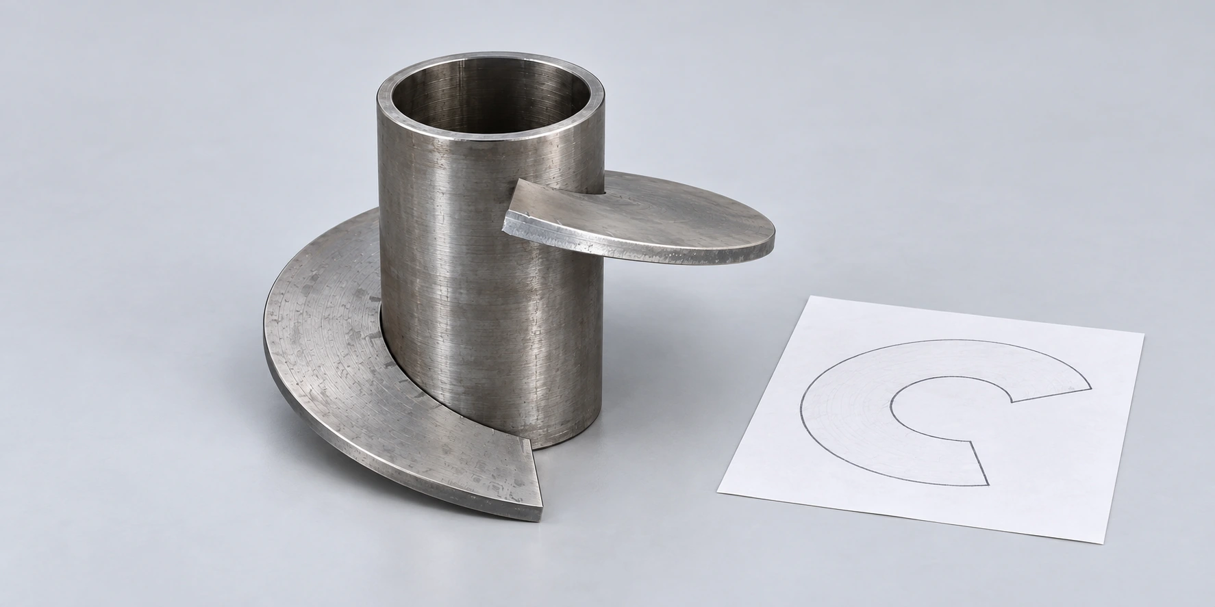
From technical review and testing to delivery and after-sales.
BOBO can assess the flight drawing and material to discuss the machine size, forming tools and positioning setup. Agree representative samples and the measurements needed for shaft fit and end alignment. Include blank-handling needs, setup instruction, maintenance and spare-tool requirements when defining the project.
Flight and flat-blank drawing review
Material and tooling-range assessment
Trial checks for pitch and assembly fit
Setup guidance and workpiece handling
BEFORE YOU CHOOSE
Focus on the individual flight and its fit in the completed screw.
Sectional forming produces individual flight pieces from prepared blanks. Continuous rolling forms a continuing helix from strip. Choose between them using the required flight section, geometry, material and the way the screw will be assembled.
Treat them as parts of one forming requirement. Material grade and the complete flight geometry determine the load and tooling conditions. Evaluate the proposed combination on the selected model rather than combining separate maximum figures.
A tool arrangement can serve a defined range, but changes in material, handedness or geometry may require adjustment or different tools. Agree the part families to be covered and the setup for each; a broad machine range is not an unlimited no-changeover promise.
Check inner and outer geometry, pitch, handedness and the alignment of the joining ends. For shafted screws, include fit against the intended pipe or shaft. These checks support assembly planning; blank cutting and welding remain separate operations.
START WITH A DRAWING OR SAMPLE
Include inner and outer diameters, pitch, thickness, handedness and the number of turns or segments per piece. Add the flat-blank drawing, shaft or pipe dimensions where relevant, and the tolerances required at the joining ends.
Provide quantities by size, the largest and most demanding parts, existing blank-cutting equipment and the planned welding or assembly method.
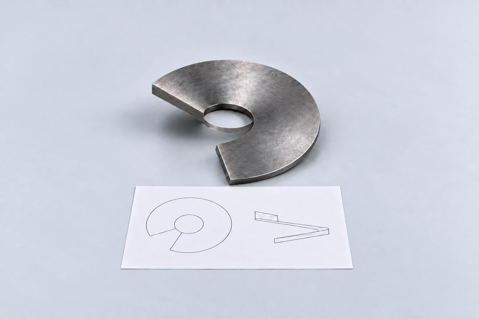
Sectional Spiral Blades Forming Machine / BOBO MACHINE