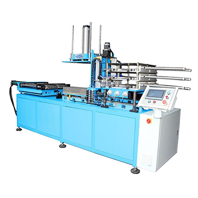
Automatic Fin Alignment And Expanding Machine
Fully automated fin alignment and tube expansion in one integrated two-station machine.
View machineFINS, FINNED TUBES & EVAPORATOR ASSEMBLY
Make the fin, form the finned tube or assemble the evaporator.
BOBO supplies fin stamping presses, strip-winding and extrusion machines for finned tubes, and fin aligning and expanding equipment for refrigerator evaporators. The range also includes CNC skiving equipment for copper and aluminum heat sinks. Each route starts with a different material form and produces a different component.
Separate fin production and tube finning routes
Manual-assisted and automatic fin assembly
Tooling matched to the fin and tube geometry
Fin Tube Machine
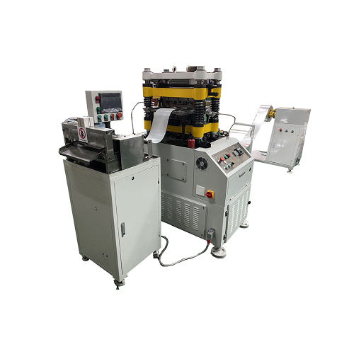
P-300/450 fin stamping press and material handling equipment
MATCH THE FIN CONSTRUCTION
Fin profile, material and tube construction define the production route. Review forming, tube finning and assembly as separate tasks.
FIND YOUR MACHINE
Choose a fin press for forming separate fins from strip, a winding machine for wrapping fin strip around a base tube, or an extrusion machine for forming fins from an aluminum sleeve over a base tube. Aligning and expanding machines assemble existing fins with tubes. The SQ-150MAX skiving machine serves a separate task: raising fins from copper or aluminum heat sink stock.
Fully automated fin alignment and tube expansion in one integrated two-station machine.
View machine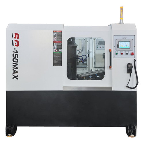
CNC precision skiving of copper and aluminum heat sink fins down to 0.05mm thickness.
View machine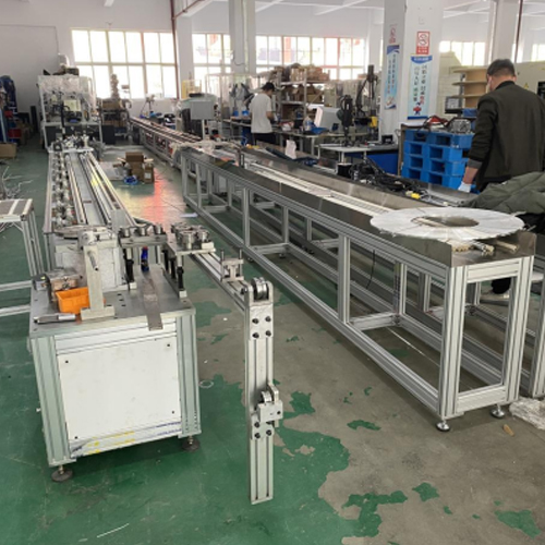
Produce double L-type finned tubes at 700 RPM with synchronized multi-section control.
View machine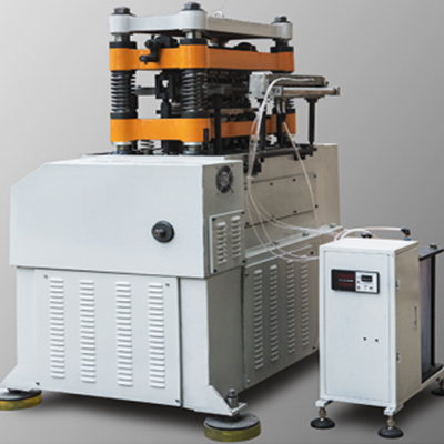
High-precision fin punching at up to 120 strokes per minute from coil to cut.
View machineHigh-precision fin stamping at up to 120 strokes per minute for heat exchanger production.
View machine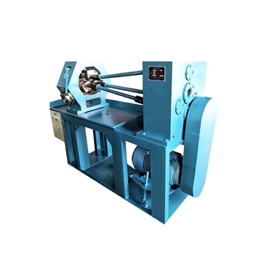
Extrude precision-formed fins onto copper, steel, or aluminum tubes in a single pass.
View machine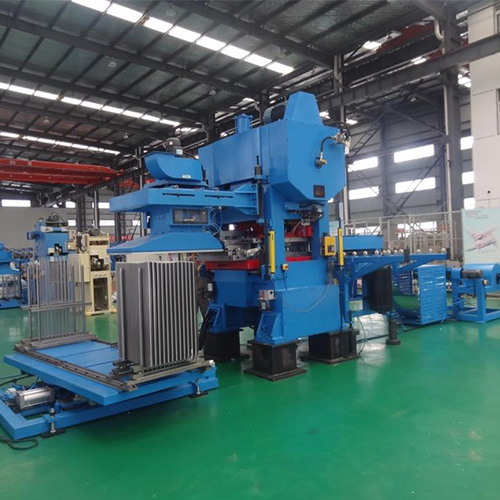
High-speed fin stamping at 120–200 strokes per minute with fully automated feeding and stacking.
View machine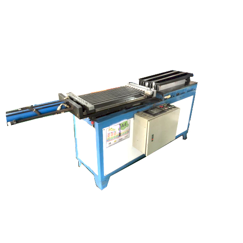
Precise fin-to-tube assembly for refrigerator evaporator production, built for reliable workshop output.
View machine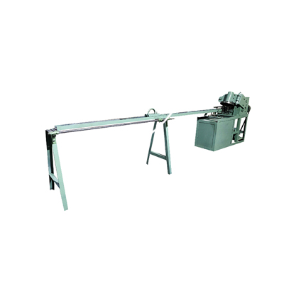
Automated spiral fin tube winding with uniform pitch and wrinkle-free L-shaped fins.
View machineWorking ranges are model-specific. Confirm material, product dimensions and the required operation against the selected machine.
PARTS & APPLICATIONS
Fin profiles, spiral-finned tubes, evaporator assemblies and heat sink bodies require different tooling and material preparation. Match the equipment to the component drawing and the steps already handled in your workshop.
01
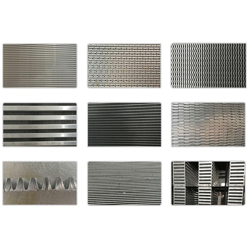
The fin press gallery shows several formed profiles. Fin height, pitch and strip thickness define the die requirement for the specified heat exchanger component.
02
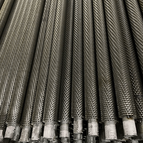
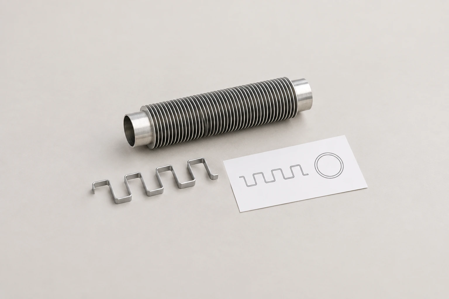
The winding-machine gallery shows finned tubes with exposed ends for later connection. Select the winding or extrusion route from the specified fin attachment and base tube construction.
03
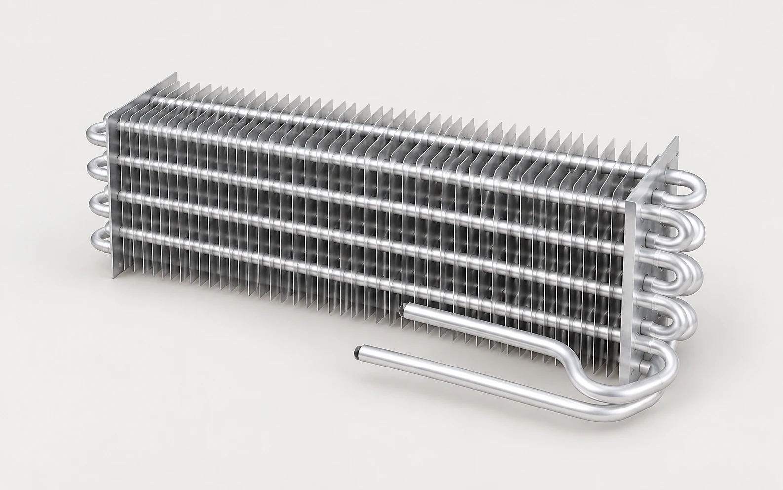
Prepared fins and aluminum tubes are aligned and expanded into evaporator assemblies. The fin hole layout, row spacing and tube arrangement determine the assembly fixture.
04
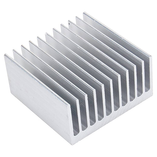
Copper and aluminum heat sink stock can be skived to raise fins from the base material. The illustrated heat sink profile is from the SQ-150MAX gallery; fin spacing, height and base dimensions guide the tooling review.
SELECTION GUIDE
A fin press, a tube finning machine and a fin assembly machine are not interchangeable. The finished cross-section establishes the route; material thickness, fin spacing and the way parts are loaded then determine the tooling and machine arrangement.
01
Separate strip-formed fins, wound fin tubes, sleeve-extruded fin tubes, assembled evaporator cores and skived heat sinks use different machines. Choose the required component cross-section first, then identify which manufacturing steps your project needs.
02
Match fin material and thickness to the forming operation. For tube finning, review the base tube and strip or sleeve together; for assembly, match the tube pattern to the fin holes. These dimensions establish the tooling, supporting fixtures and changeover requirements.
03
Compare strip supply and collection on a fin press, long-tube support on a winding machine, and manual tube insertion on an assembly machine. Include these activities in the production cycle so the selected machine fits the work before and after it.
Keep the heat exchanger design and the manufacturing checks connected: fin geometry and tube-to-fin contact matter, but machine specifications alone do not establish the thermal performance of a completed exchanger.
YOUR FINISHED PART
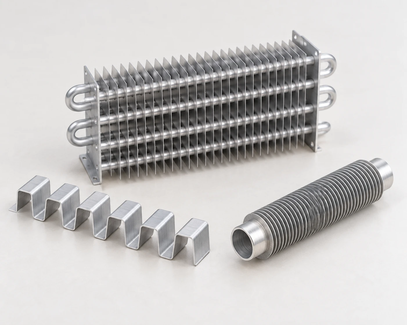
Include the material, dimensions and acceptance requirements.
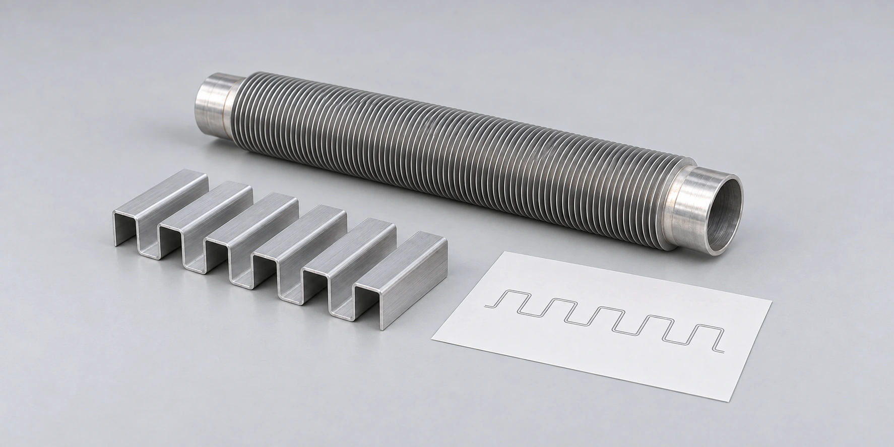
From technical review and testing to delivery and after-sales.
BOBO can review the component drawing, propose the relevant machine and tooling, and plan a material trial. Set inspection points for fin shape, spacing and assembly fit before testing. For a combined project, include strip handling, tube support and transfer between machines in the layout and supply scope.
Fin profile, material and tooling review
Trial checks for fin geometry and assembly fit
Coil handling, tube supports and machine interfaces
Tooling changeover, operator training and spare-part planning
BEFORE YOU CHOOSE
These distinctions help separate fin-making, tube-finning and assembly requirements in a quotation.
A winding machine forms and wraps a separate strip around a base tube; BOBO lists L-type winding equipment. The E-50 extrusion machine works with an aluminum sleeve over a copper or steel base tube and rolls the sleeve into fins. The starting materials, fin attachment and tooling are different, so select the route from the required tube construction.
These machines start with prepared fins and aluminum tubes and assemble them into refrigerator evaporator cores. Fin stamping is a separate operation. The fin hole pattern, row arrangement and tube dimensions must match the assembly tooling; adding an assembly machine does not replace the fin press.
The operation depends on the model. The vertical automatic machine uses suction pickup and servo positioning for the fins. The two-station assembly machine still requires an operator to insert tube sets using a guide plate before the automatic sequence. The manual-assisted model combines manual insertion with hydraulic expansion. Compare the complete loading and unloading cycle as well as the automatic motion.
The listed fin forming presses allow die changes for different fin sizes and profiles. A new pattern needs compatible tooling and a material trial; changing a control setting alone does not create a different fin shape. Review the press, strip feed and cutting or collection equipment together when adding another product.
Include the tube support arrangement in the quotation review. The double L-type winding machine lists the main unit and control cabinet, while its front and rear feeding and discharge brackets are outside that stated supply scope. Tube length and workshop layout therefore affect the equipment needed around the winding head.
START WITH A DRAWING OR SAMPLE
Include material grades and thicknesses, fin height and pitch, component width and length, and the required output. For finned tubes, add base tube diameter and wall thickness plus the fin strip or sleeve dimensions. For evaporator assembly, include the fin hole pattern, tube layout and assembly length.
Identify the steps already available in your workshop and include samples or drawings of the fin profile, heat sink body or tube assembly you want to produce.
Fin Tube Machine / BOBO MACHINE