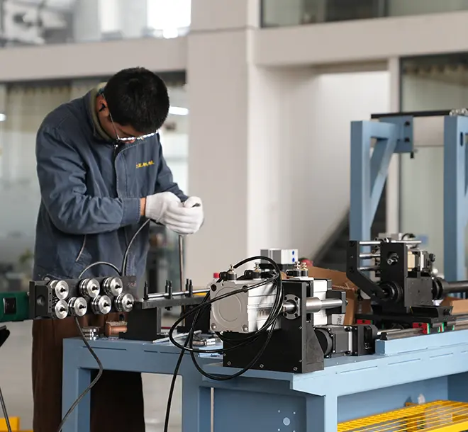
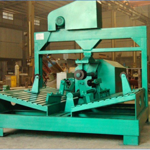
Axial Fan Front Disc Spinning Machine
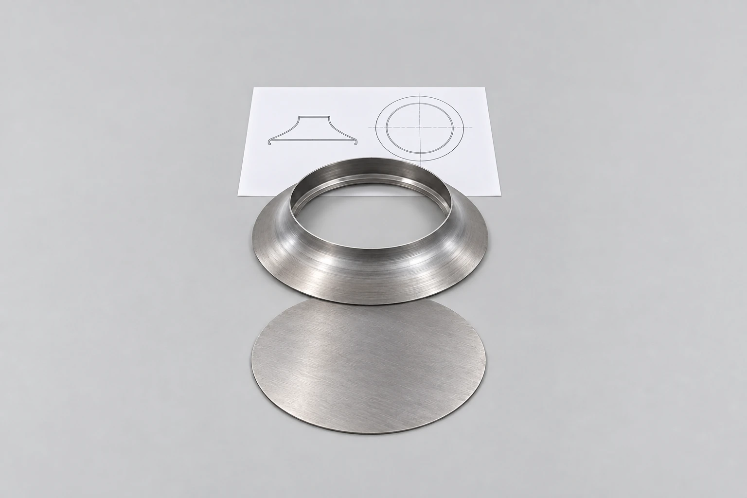
Spin-form axial fan discs up to 3000mm — replacing costly hydraulic press tooling.
View machineFAN COMPONENTS & DUCT CONNECTIONS
Form casing flanges, fan components and duct connectors.
BOBO supplies vertical and horizontal machines for axial fan casing flanges, spinning equipment for fan inlets and front discs, and separate TDC flange-profile and corner-production equipment. Start with the component: a circular casing edge, a spun fan part or a rectangular duct connection requires a different forming route.
Vertical and horizontal casing flanging
Fan inlet and front-disc spinning
TDC profile forming and corner stamping
Fan Flange Machine
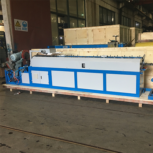
TDC duct flange roll former
DEFINE THE CONNECTION PROFILE
Component shape, material thickness and the mating fit.
FIND YOUR MACHINE
For cylindrical fan casings, compare the vertical and horizontal flanging models by workpiece dimensions and edge shape. The spinning machine shapes sheet blanks for inlet and front-disc parts. TDC equipment serves a separate task: rolling flange profiles from coil or stamping corner pieces with a feed-and-press line.
Spin-form axial fan discs up to 3000mm — replacing costly hydraulic press tooling.
View machineContinuous TDC flange forming and cutting in one integrated production line.
View machine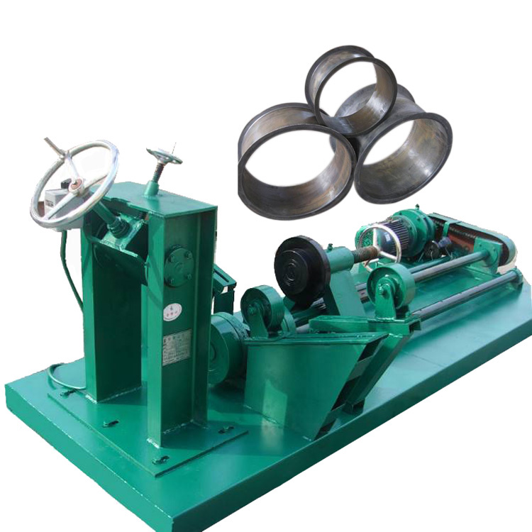
Form precise fan flanges on 300–1250mm diameter parts in a single horizontal pass.
View machine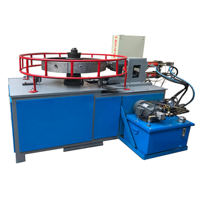
Form axial fan casings in 20 seconds with hydraulic vertical flanging precision.
View machine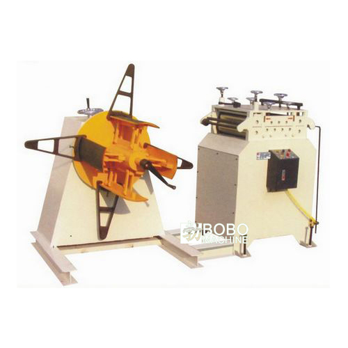
Automated coil-to-corner punching at 45 pieces per minute for rectangular duct production.
View machineWorking ranges are model-specific. Confirm material, product dimensions and the required operation against the selected machine.
PARTS & APPLICATIONS
Circular fan parts and rectangular duct connections have different mating surfaces and assembly requirements. Use the finished component drawing to identify the forming operation and its tooling.
01
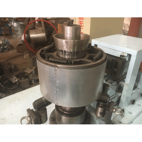
Vertical and horizontal flanging machines form the edge of a cylindrical fan casing. The casing diameter, height, wall thickness and required flange section guide the tooling and support arrangement.
02
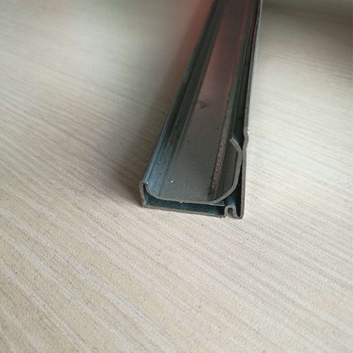
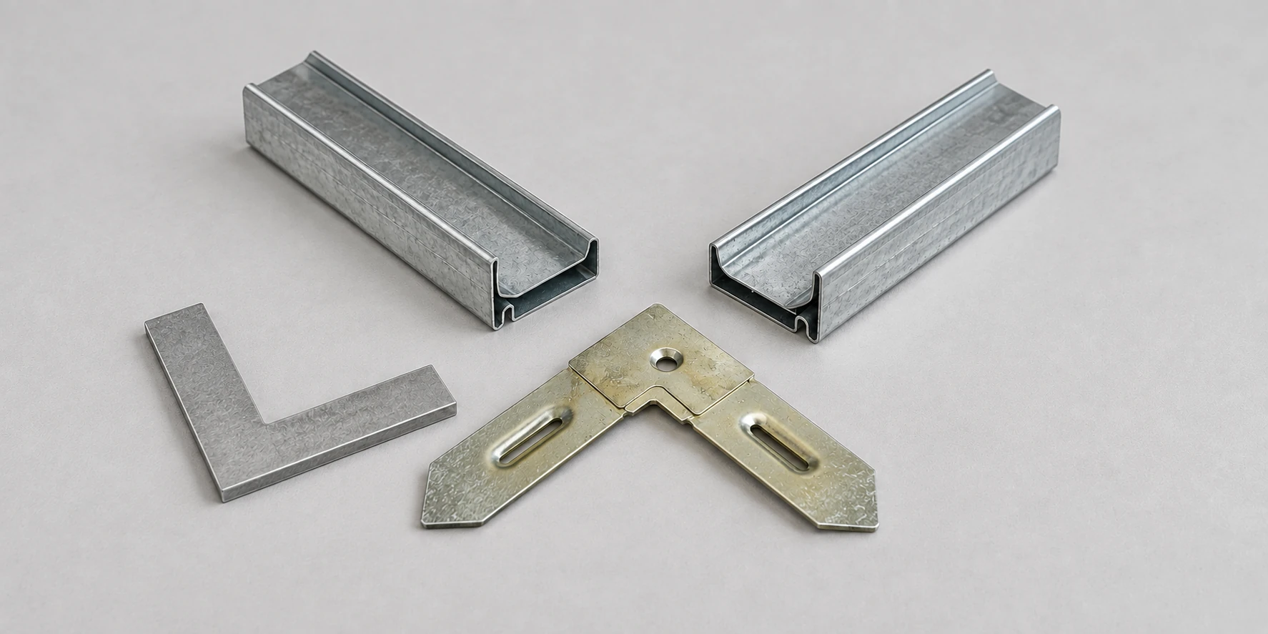
Roll-formed connector lengths are assembled into frames for rectangular duct joints. Match the profile section and cut length to the corner pieces and duct connection design.
03
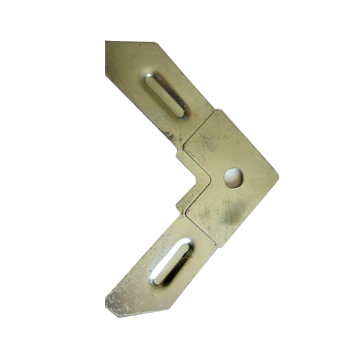
The coil-fed corner line combines strip straightening, feeding and press work. The corner drawing defines the outline, formed features and mating fit required from the tooling.
04
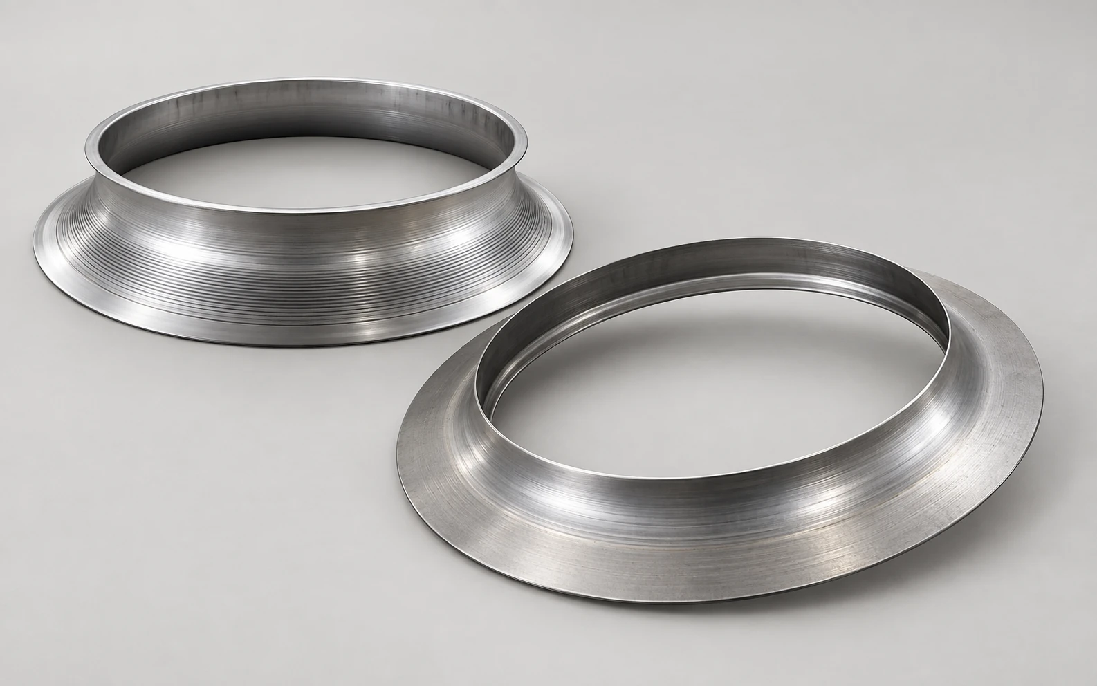
The spinning route shapes sheet material progressively over a mold for fan inlet contours and centrifugal-fan front discs. The required cross-section determines the blank, mold and forming sequence.
SELECTION GUIDE
A casing flange is formed on an existing cylindrical edge; a TDC profile is produced as a separate connector. Fan inlet and front-disc shapes add another tooling task. Diameter or sheet thickness alone cannot distinguish these processes.
01
Start with the casing edge, spun contour or connector cross-section and its mating part. Include flange height, radii, profile dimensions and any hole pattern so the tooling is based on the complete component.
02
Review grade and thickness together with casing or blank size. Distinguish an already-formed cylinder, a sheet blank and coiled strip. These inputs lead to different clamping, feed and forming arrangements.
03
Plan loading, unloading and tool changes as well as forming. For connector production, include cutting, corner manufacture and frame assembly. Compare output over the complete workflow, rather than using a press-stroke or roll-feed rate alone.
Plan the next operations alongside forming. Hole-making, profile-frame assembly, attachment to the duct and sealing each need a defined place in the production sequence.
YOUR FINISHED PART
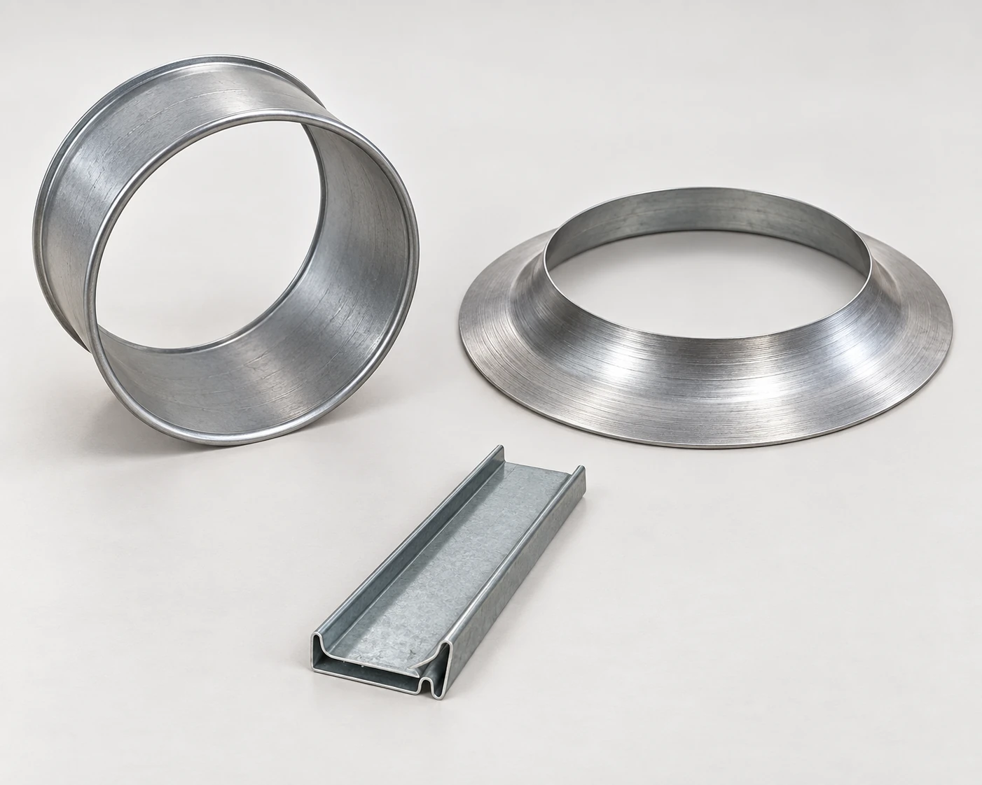
Include the material, dimensions and acceptance requirements.
From technical review and testing to delivery and after-sales.
Work with BOBO on the casing edge, spun contour or connector drawing and the material to be formed. Define the required rolls, molds or corner dies, then agree sample checks for fit and geometry. Include blank preparation, loading access, tooling changes and operator training in the project scope.
Component section and mating-fit review
Flanging rolls, spinning molds or corner dies
Material trials and dimensional checks
Loading, changeover and training arrangements
BEFORE YOU CHOOSE
Clarify whether you need a formed casing edge, a spun component or a separate duct connector.
These are different jobs in this range. Fan flanging equipment works on the edge of a cylindrical casing. The TDC roll former feeds strip through forming rolls and cuts the resulting connector profile. The TDC corner line makes the separate stamped pieces used in the connection.
Compare casing diameter and height, material thickness, flange shape and the way the part is supported and loaded. Machine orientation changes the handling arrangement and floor layout. Select around the intended casing and trial, rather than assuming that one orientation gives better flange quality for every part.
Treat the bolt-circle diameter, hole pattern and hole-making operation as explicit requirements. Forming the casing edge does not by itself provide the mounting holes. The duct-corner press line is a separate product for stamped corner pieces; it is not a bolt-hole unit for circular fan casings.
The roll former decoils material, forms the flange profile and cuts it to length. The cut profiles are then assembled with corners and attached to the duct, followed by the required sealing work. Specify those downstream tasks separately when planning the connection-production workflow.
START WITH A DRAWING OR SAMPLE
For fan parts, send a section drawing with casing or blank dimensions, flange or inlet contour, material grade, thickness and tolerances. For duct connectors, include the profile and corner drawings, strip specification and cut lengths. Add batch sizes and required output.
Identify existing blank preparation, hole-making and assembly equipment, plus the loading method and available workshop space.
Fan Flange Machine / BOBO MACHINE