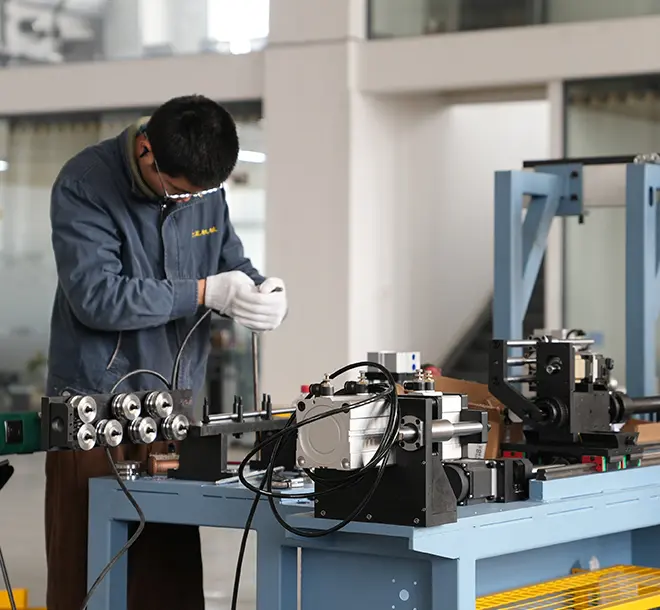
Bowden Cable Outer Casing Production: From Wire Flattening to Coiling
Jump to section
A Bowden cable outer casing begins as round steel wire and ends as a spiral tube that has to hold its shape under load. Two operations decide whether it does that job: flattening the wire to an exact profile, then winding it into a helix at controlled pitch and tension. Get the flattening tolerance wrong and the coils sit unevenly. Get the pitch wrong and the casing collapses the first time the cable is pushed. This article follows the casing through both stages, then covers how wind type is matched to the cable’s job.
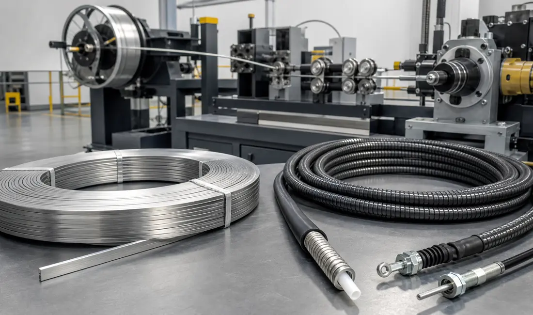
A Bowden cable outer casing is a spiral-wound steel tube that guides the inner wire and absorbs the reaction force when the cable is operated. Flattened wire is used because a flat profile spreads compressive load across a wider contact face than round wire of the same section, so the casing resists collapse while staying flexible. The two sections below cover how the casing is layered and what it is made from.
A finished casing has three layers, and each one solves a different problem.
The inner lining comes first. It is a thin plastic tube, usually nylon or PTFE, and it gives the inner wire a low-friction surface to slide against. Without it, steel runs on steel and control feel degrades quickly.
The wound wire layer sits over the lining and does the structural work. It carries compressive load when the cable is pushed and holds the routing path when the cable is bent.
The outer sheath closes the casing. Extruded plastic keeps dirt and moisture out of the wire layer and protects it from abrasion in service.
Steel is standard, and the grade follows the environment rather than the load. Galvanised steel covers most automotive and industrial work. Stainless steel is specified where the cable sees salt spray, washdown, or chemicals.
Cross-section matters as much as grade. Round wire bends more easily and suits tight routing. Flat wire holds up better in compression because the load spreads over a broader face, which is why push-capable casings use it.
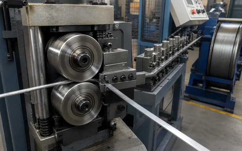
Flattening turns round wire into a rectangular strip sized for spiral winding. A dedicated machine straightens the wire, presses it between rollers, and holds the finished section to a tight tolerance. The sections below cover the forming step first, then dimensional control.
Flattening works by progressive compression rather than cutting. Round wire passes between two counter-rotating pressing rollers that squeeze it from opposite sides, and the circular section spreads into a rectangular strip. Production machines take round wire from about 0.5 mm up to 2.5 mm and can also press T-shaped and triangular profiles from the same stock.
Roller material sets the running cost. Carbide alloy rollers hold their surface far longer than tool steel and run without water cooling, which removes coolant handling and filtration from the workshop entirely.
Speed is matched to the line, not maximised. A wire flattening machine in the WF-200 size runs at 1.2 m/s and above on wire up to 1.7 mm, while the WF-250 runs at 1.5 m/s and above on wire up to 2.5 mm. A Mitsubishi inverter gives stepless control from 0 to 50 Hz, so output can be matched to whatever the winding station downstream can absorb.
Flattening also work-hardens the steel. That is useful rather than a side effect, because the harder strip resists deformation once it is wound into the casing.
Tolerance is the specification that everything downstream depends on. Both machine sizes hold flattened wire to ≤±0.01 mm, which is what the winding station needs to lay turns without gaps or overlaps.
Straightness comes before tolerance. An integrated straightening unit removes coil memory and minor bends before the wire reaches the rollers, since a wire that arrives bent flattens unevenly no matter how well the rollers are set.
Feed faults are caught by sensor rather than by eye. A monitoring system detects breakage or tangling, sounds an alarm, and stops the machine, which protects the rollers and keeps defective strip out of the next process.
Bobbin capacity decides how often the run stops. A 110 kg bobbin keeps the line going through long production runs and cuts changeover frequency, which matters more to real output than peak speed does.
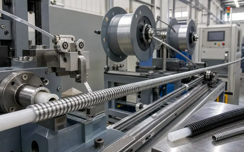
Winding turns flat strip into the casing itself. The strip is laid helically over a mandrel or an inner plastic hose, the pitch is set, and the finished tube is cut and sheathed. Each step below feeds the next, so tension set at the start shows up as compression strength at the end.
The mandrel sets the bore. It is a cylindrical rod sized to the finished inner diameter, and it turns on a driven spindle while the strip wraps around it. On lines that wind directly over an inner plastic hose, the hose itself takes the mandrel’s place and stays in the finished casing.
A guide system positions the strip against the mandrel at the correct angle, and each turn lands beside the one before it. Feeding can run in manual or automatic mode depending on the product, and an alarm stops the line if wire or inner hose feed is interrupted.
Tension control decides casing quality more than speed does. Too little tension leaves loose turns that compress under load. Too much deforms the strip or breaks it. Constant tension from full bobbin to empty is what keeps the coil uniform along the whole length.
Pitch is the axial distance between the centres of adjacent turns, and it controls how much push the casing survives. A tight pitch leaves almost no space between turns, so load transfers from turn to turn instead of closing the gaps.
Flexibility moves the other way. Opening the pitch lets the casing bend to a smaller radius, but it also gives the coils room to close under compression, which costs stroke at the output end.
Consistency matters as much as the setting itself. Pitch is held constant by geared advance of the strip guide, because a section wound at a wider pitch becomes a weak point where compression concentrates in service.
The wound casing leaves the mandrel and is cut to the ordered length, either inline or on a separate cutting station.
Diameter is then verified at several points along that length. Inner diameter governs how freely the inner wire slides, and outer diameter governs whether the sheath extrudes evenly, so both are checked rather than one.
The sheath goes on last. PVC, nylon, or polyethylene is extruded over the wire spiral to seal the coil and give a clean outer surface. Thicker sheathing protects better but stiffens the casing, so the specification follows the routing as much as the environment.
Finished casings are then tested. A compression test confirms the casing holds its shape under axial load, and a repeated bend test at the minimum radius checks for turn separation or sheath cracking.
Wind type follows load direction. Close-wound casing places turns tight against each other and carries compression, while long-lay casing lays wire at a shallow angle with space between turns and suits pull-only work. The sections below cover construction, then the trade-offs, then selection.
Close-wound casing is a tightly coiled helix with adjacent turns touching or nearly touching. The result is a dense tube with no visible gaps and an almost perpendicular turn angle to the casing axis.
Long-lay casing runs its wires along the casing at a much shallower angle, with clear spacing between passes. The structure is open and behaves more like a bundle of parallel wires than a coil.
The difference in behaviour follows directly from that geometry. Close-wound turns push against each other end to end, so the casing supports compression. Long-lay wires have nothing to push against, so they carry tension well and offer almost no support in compression.
| Attribute | Close-wound | Long-lay |
| Compression support | High | None |
| Bending flexibility | Moderate | High |
| Internal friction | Higher | Lower |
| Sealing against dirt and water | Good | Poor |
| Wire used per metre | Higher | Lower |
| Suits push loads | Yes | No |
Neither type wins outright. Close-wound casing buys compression strength and sealing at the cost of flexibility and material. Long-lay casing buys flexibility and lower cost by giving up push capability completely.
Close-wound casing suits any cable that pushes as well as pulls, including brake, clutch, and gear shift cables. It also suits dirty or wet service, such as marine equipment, off-road vehicles, and outdoor machinery, because the closed surface keeps contamination out of the inner wire.
Long-lay casing suits pull-only cables, including throttle cables, hood release cables, and seat adjustment cables. It also suits routes with tight bends and high cycle counts, such as bicycle brake and derailleur cables, where low friction is what the rider actually feels.
Specifying long-lay for a push application is the most common casing mistake, and it shows on the first test as a control that feels soft and loses stroke.
Winding faults usually start upstream. Strip that varies in thickness lays unevenly, which leaves gaps in some sections and overlaps in others, and no winding setting corrects that afterwards. Holding the flattening tolerance is what makes consistent pitch achievable.
Pitch is checked by marking the casing and measuring the axial distance across a set number of turns, then comparing that figure with the drawing. Doing it on a sample from each bobbin catches a slipping feed or falling tension before a full run is affected.
Yes, provided the mandrel and strip guide can be changed and the flattening rollers reset to the new profile. Most producers group orders by casing diameter, since fewer changeovers usually gain more output than running any single station faster.
Outer casing quality is decided in two places. The flattening station has to deliver strip within tolerance, and the winding station has to lay that strip at constant tension and pitch. Everything after those two steps, including sheathing and final testing, only inherits the result.
Equipment choice follows the product. Wire diameter, casing bore, wind type, and output per shift set the line, and the flattening machine should be sized to the largest wire the range will ever use. Share cable drawings, wire and casing sizes, and target output through the contact page, and the engineering team can confirm a suitable line layout.