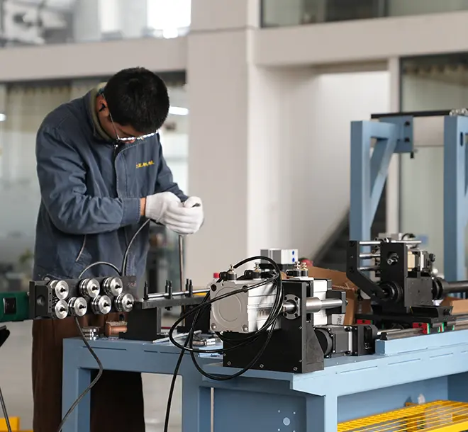
Push-Pull Cable Manufacturing: Liner Extrusion to Assembly Explained
Jump to section
A push-pull cable moves a lever at one end of a machine by pushing or pulling a wire at the other. Getting that motion to arrive intact depends on how the cable was built. An uneven liner wall adds friction, loose armor lets the conduit collapse under load, and a badly swaged terminal slips before the wire ever reaches its rated pull. This article follows a push-pull cable through production, from liner extrusion to the finished, tested assembly. It also covers how conduit type is matched to the load and the routing.
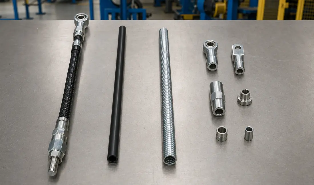
A push-pull cable is a mechanical control assembly that transmits force in both directions through a supporting conduit. Five parts do the work. An inner core carries the load, a liner lets it slide, and a conduit stops it buckling. Conduit fittings anchor the casing, and core end fittings connect to the lever or actuator. The two sections below cover what each part does and what it is made from.
The inner core carries every push and pull force in the assembly. Solid wire suits short, straight runs, while stranded wire rope bends around corners and still resists compression, which is why most routed cables use it.
The liner sits between the core and the conduit wall. It is a thin plastic tube, usually high-density polyethylene, and it gives the core a low-friction surface to slide along. Without it, steel runs against steel and control precision drops within a few thousand cycles.
The conduit does the job that makes push possible at all. A bare wire buckles the moment it is pushed, so the conduit supports it along its whole length and holds the routing path.
Fittings close the loop at both ends. Conduit fittings anchor the casing to a bracket, and core end fittings, such as ball studs, threaded ends, or clevis ends, connect the core to the moving part. Zinc die-cast fittings cover standard loads at lower cost, while machined steel fittings handle higher loads and higher temperatures.
Clearance between core and conduit decides how the cable feels in service. Too little clearance drags and heats the liner. Too much lets the core wander and buckle under push, which shows up as lost stroke at the output end.
Material choice follows the operating environment rather than the load alone. Carbon steel core wire is standard, while stainless steel resists corrosion in marine and washdown use, and galvanised wire suits outdoor equipment.
Conduit construction splits the same way. Steel armor carries high loads, and plastic-jacketed conduit saves weight where loads are moderate and corrosion is the bigger risk.
Production runs in three stages: extrude the liner, wind the armor over it, then apply the outer jacket. Each stage feeds the next, so a fault in the liner shows up as friction in the finished cable.
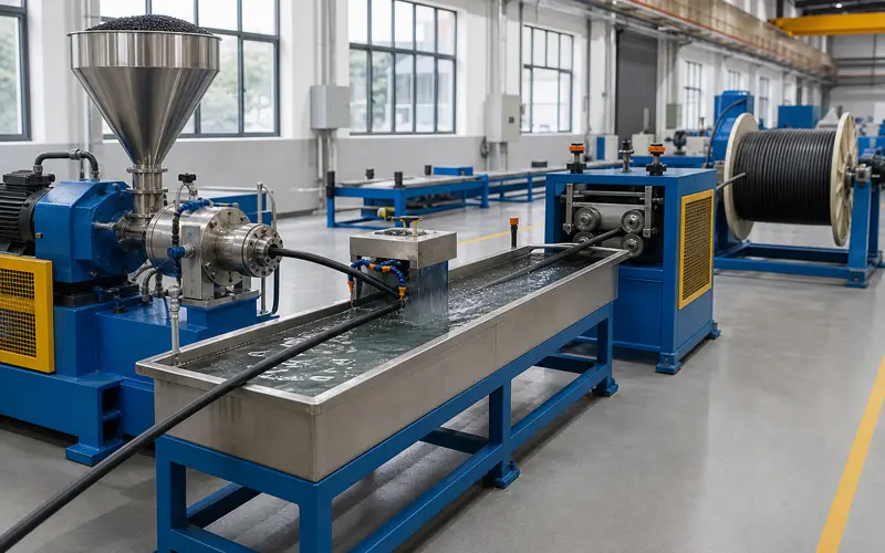
Extrusion starts at the hopper. Plastic granules feed into a heated barrel, where a rotating screw softens them and drives the melt forward to the die. The die shapes the melt into a continuous tube sized to the core it will carry.
A vacuum tank and water bath then set the shape. Vacuum holds the bore open while the tube is still soft, and the cooling water fixes the dimensions before the tube reaches the haul-off. Even cooling matters here, because a tube that cools faster on one side warps and loses roundness.
Wall thickness is the specification to hold. A thin spot wears through early, and a thick spot narrows the bore and drags on the core. Inline checks on bore size and wall thickness catch drift before a whole spool goes to scrap.
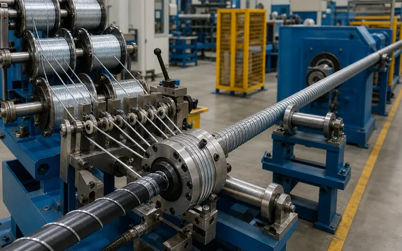
Armor winding adds the layer that resists compression. A winding head carries several spools on a rotating cage and lays wire or flat strip helically over the liner at a set angle and tension.
Lay angle sets the balance between stiffness and flexibility. A tighter lay resists push loads better, but it stiffens the cable and raises the minimum bend radius. The angle is therefore set against the routing drawing, not the load alone.
Tension control matters as much as angle. If tension drops as the spool empties, the armor loosens and the conduit compresses under push. Torque-controlled feed keeps pulling force constant from full spool to empty, and an inline laser gauge watches the finished outer diameter and alarms when it drifts.
Rotary swaging follows on armored constructions. It compresses the wound strip into a tight, even armor layer on the line, which removes a separate downstream operation. An armored push-pull cable making machine handles cables in the 2.0 to 3.5 mm range at over 110 metres per hour, using stainless strip around 0.35 by 2.0 mm.
The outer jacket seals the armor and holds it in place. A second extruder coats the wound layer, or a pre-made casing is wound over it where throughput matters more than finish.
Jacket material follows the environment. PVC costs less and performs well indoors, and polyethylene holds up better against sunlight and moisture outdoors.
Jacket thickness is a trade-off, not a maximum. A heavier jacket protects better but stiffens the cable, so outdoor and under-vehicle cables carry more of it than enclosed indoor runs.
The core is drawn, stranded, plated, then cut and swaged to its terminals, and the finished assembly is tested before it ships. Core production comes first, then terminal attachment, then testing.
Drawing sets the core diameter. High-carbon steel wire passes through progressively smaller dies, which work-hardens the steel and leaves a smooth surface that slides cleanly inside the liner.
Stranding turns those wires into rope. A wire rope tubular stranding machine twists wires around a centre wire in a fixed pattern, and common constructions include 7×7, 7×19, and 1×19. More wires give more flexibility at a given diameter, while fewer and heavier wires give a stiffer core that pushes better.
A surface treatment finishes the core. Zinc plating protects against corrosion, and a thin polymer coating lowers friction against the liner. The finished core has to slide freely and still stay stiff enough to push without buckling.
Swaging locks the terminal to the wire. The core end passes into a metal terminal, and a press compresses the terminal around it until the joint holds more than the wire itself will carry.
The sequence is short and worth following exactly. Cut the core to length, seat the end fully into the terminal, then position it in the die. Apply pressure, then check the swaged diameter against the drawing. A terminal seated only part way is the most common cause of pull-off failures.
Conduit ends are finished the same way. Zinc die-cast or machined steel fittings slide over the casing and are crimped or moulded in place. Threaded fittings screw onto prepared conduit ends where the joint has to be removable.
Assembly brings the two halves together. The fitted core threads into the conduit without scoring the liner, and lubricant between core and liner lowers running friction from the first cycle.
Testing then proves the assembly. A pull test loads the terminals above the working load to confirm nothing slips. A function test then cycles the cable through its full stroke while push and pull forces are measured. Cables that pass carry an identification tag through packing, so the build record stays with the part.
Conduit type follows load and bend radius. Round-wire conduit handles moderate push loads and tighter bends, flat-wire conduit carries the highest push loads in straighter runs, and braided conduit suits pull-only work in tight spaces. The sections below cover construction first, then the trade-offs, then selection.
Round-wire conduit is a close-wound coil of round wire. Each turn sits against the next, which gives a tube with even inner and outer diameters and good all-round flexibility.
Flat-wire conduit uses rectangular wire wound the same way. The flat profile lets each turn nest into the one before it, and that interlock makes a stiffer tube that resists compression better than round wire.
Braided conduit weaves strands across the axis instead of coiling them around it. The weave bends through tight, complex routes, but it offers almost no support in compression.
| Attribute | Round wire | Flat wire | Braided |
| Compression support | Moderate | Highest | None |
| Minimum bend radius | Tight | Largest | Tightest |
| Stroke accuracy under push | Good | Best | Not applicable |
| Relative tooling cost | Lowest | Highest | Moderate |
| Suits push loads | Yes | Yes | No |
No single type wins on both axes. Flat wire buys compression strength at the cost of a larger bend radius. Braid buys routing freedom by giving up push capability entirely. Round wire sits between the two.
Stroke accuracy tracks the same trade-off. A conduit that compresses under push absorbs part of the input stroke, so the output moves less than the input. This is why precise controls favour flat wire even at moderate loads.
Round-wire conduit suits assemblies that push and pull at moderate loads through several bends, such as automotive throttle and gear cables, industrial actuator controls, and marine control cables.
Flat-wire conduit suits high push loads and precise movement, such as heavy equipment controls, agricultural machinery, and clutch and brake cables where the run is mostly straight.
Braided conduit suits pull-only cables in tight spaces, such as emergency release cables, safety lockouts, and door release mechanisms. Specifying braid for a push application is the single most common conduit mistake, and it shows up as a control that feels soft from the first test.
Stroke loss usually comes from three sources. Liner wear widens the bore and lets the core wander. Armor that was wound at falling tension compresses under load. A terminal that was under-swaged creeps at the joint. Measuring input and output stroke on a sample from each batch shows which one is drifting.
Lay length is checked by marking the armor and measuring the axial distance over one full turn. Comparing that figure against the drawing catches a slipping feed or a loose spool before the run continues.
One line can produce both, provided the winding and swaging stations can be bypassed for non-armored constructions. Extrusion, stranding, and terminal work are shared in either case, so most builders size the extrusion and stranding capacity first.
Push-pull cable quality is decided in three places. The liner needs an even wall, the armor needs constant winding tension, and the swage needs to grip the core without crushing it. Everything downstream inherits those three results, which is why in-process checks on bore size, outer diameter, and swage diameter catch more problems than final inspection ever will.
Equipment choice follows the product, not the reverse. Core diameter, armor material, conduit type, and output per shift set the line. BOBO Machine builds liner extrusion, armor winding, rotary swaging, and stranding equipment for control cable production. Share cable drawings, core and conduit sizes, and target output through the contact page, and the engineering team can confirm a suitable line layout.