Terminal Crimping Quality: Predicting Failure with Pull-Force and Cross-Section
Jump to section
Terminal crimp quality depends on two critical measurements: pull-force testing validates the mechanical retention strength between the wire and terminal, while cross-section analysis reveals the internal metal-to-metal contact area that determines long-term electrical and mechanical reliability. Both tests predict different failure modes, and manufacturers who rely on only one method miss defects that cause field failures in automotive, medical, and industrial wire harnesses.
Pull-force testing measures how much force a crimped terminal can withstand before the wire pulls free. Cross-section analysis cuts the crimp open to inspect crimp height, conductor deformation, and the presence of voids or birdcaging inside the barrel. Neither test alone guarantees a defect-free connection.
This article explains what each test measures, how to interpret the data against IPC/WHMA-A-620 and USCAR-21 standards, and how to combine both methods to eliminate failures before assemblies leave the factory.
Terminal crimping quality depends on compression ratio, metallurgical contact formation, and dimensional tolerances — not just mechanical retention. Visual inspection and basic continuity tests miss microscopic air pockets and contact zone degradation that cause field failures.
A proper crimp creates metal-to-metal contact through plastic deformation, not friction alone. When the terminal barrel compresses conductor strands to 75-85% of their original cross-section, the force exceeds the yield strength of both materials. This creates cold welding at thousands of micro-asperity contact points where copper strands and terminal metal bond without heat.
The compression ratio determines whether these bonds form. Below 70% compression, air gaps remain between strands and barrel walls, allowing oxygen to form oxide layers. Copper oxide has much higher electrical resistance than pure copper. Above 90% compression, individual strands can be damaged, reducing current-carrying capacity and creating stress points that fail under vibration.
A gas-tight crimp maintains low contact resistance by excluding air from the contact zone. The compressed strands fill the barrel volume completely, blocking moisture or oxygen. This protection persists through thermal cycling and vibration because the cold-welded contact points do not separate.
A crimp measuring 38 Newtons instead of the required 55 Newtons passes visual inspection every time. The barrel appears properly formed, conductor strands fill the visible area, and a basic continuity meter shows low resistance at room temperature. The defect only appears after many thermal cycles, when contact resistance climbs high enough to cause voltage drop failures.
Visual inspection cannot detect incomplete cold welding. The microscopic air pockets between under-compressed strands are too small to see. Continuity testing at room temperature misses the problem because contact pressure alone creates enough surface contact for a low resistance reading under static conditions.
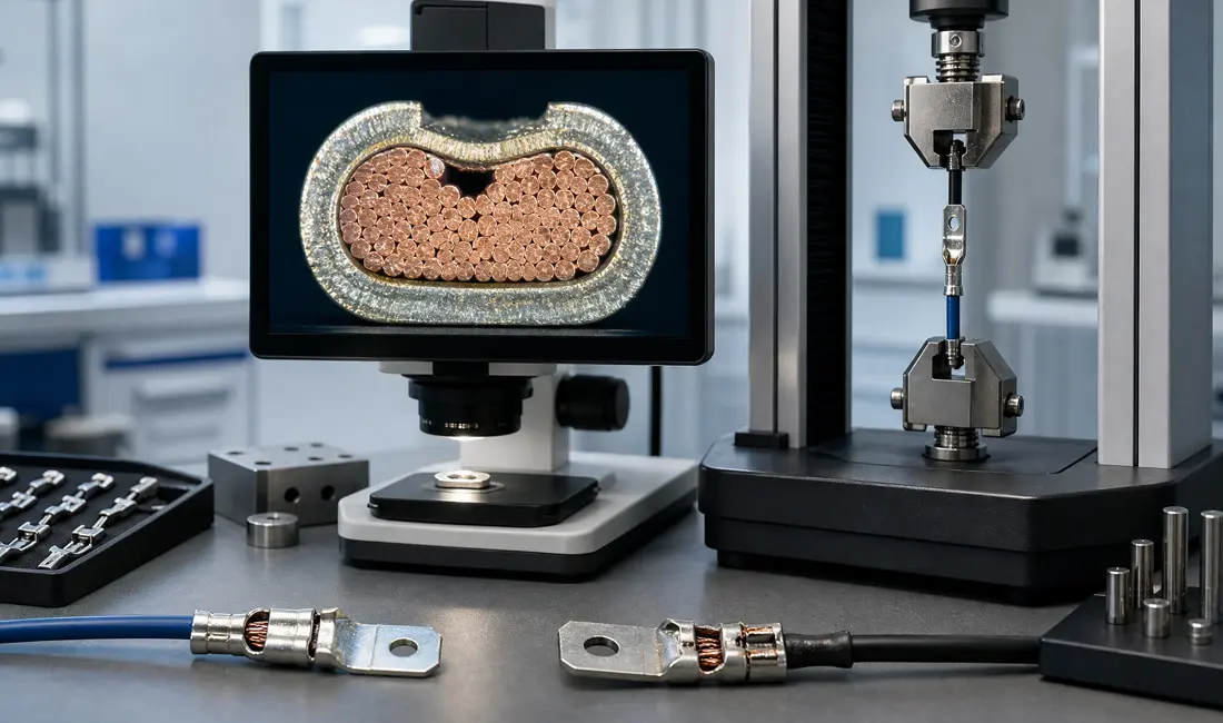
Cross-section analysis reveals these defects. Cutting through the crimp zone and examining it under magnification shows conductor strand deformation, bell-mouth formation at the barrel edges, and strand-to-barrel contact percentage. IPC/WHMA-A-620 requires a minimum strand contact area in the cross-section for Class 2 and 3 assemblies. Pull-force testing validates mechanical retention, but only cross-section analysis confirms gas-tight contact formation.
Pull-force testing predicts crimp failure by measuring the mechanical strength of the wire-to-terminal connection before it enters service. A crimp that fails below the minimum force threshold will likely fail in the field under vibration, thermal cycling, or normal stress.
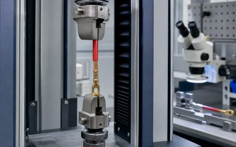
Pull-force testing measures the tensile strength required to separate a crimped terminal from its wire. The test applies a controlled longitudinal force until the terminal pulls off or the wire breaks.
A pull tester secures the wire in an upper grip and the terminal in a lower grip. The motorized crosshead pulls at 25 mm per minute according to IPC/WHMA-A-620 standards. A load cell records the peak force at failure.
Three failure modes occur during testing. Wire break means the conductor strands fracture before the crimp releases. Terminal pull-off means the terminal separates from the wire, which is acceptable only if the force exceeds the minimum specification. Partial strand pull-out means some strands remain crimped while others release, suggesting improper crimp parameters.
The minimum acceptable pull force varies by wire gauge. A 20 AWG wire requires 13 pounds of force minimum. A 16 AWG wire requires 25 pounds. Class 3 applications for aerospace and medical devices require pull forces at 90% of the wire’s ultimate tensile strength.
Under-crimping creates insufficient compression between the terminal barrel and conductor strands. The contact area remains too small to generate adequate mechanical bonding. The terminal slides off the wire at low force because the strands are not gripped tightly enough.
Over-crimping applies excessive force that severs individual conductor strands. The damaged strands cannot contribute to the connection’s mechanical strength. A 20 AWG wire with seven strands loses significant tensile strength for each severed strand.
Crimp height measurement reveals both conditions. A crimp height above specification indicates under-crimping. A crimp height below specification indicates over-crimping. Each terminal and wire combination has a target crimp height range.
Pull-force testing cannot detect internal voids or gaps between conductor strands. A crimp may pass pull testing but still contain air pockets that increase electrical resistance. These voids reduce the contact surface area available for current flow.
The test does not measure the gas-tight quality of the metal-to-metal interface. Oxidation occurs when air reaches the crimp interface, degrading conductivity over time. A crimp with adequate mechanical strength may fail electrically after months in service due to corrosion.
Pull testing cannot identify strand alignment issues within the terminal barrel. Crossed or twisted strands may provide sufficient tensile strength but create current concentration points. These hot spots accelerate insulation breakdown in high-current applications.
The test provides no information about the insulation crimp quality. The insulation support must be cut open before testing to isolate conductor crimp strength. A terminal with excellent conductor crimp strength but poor insulation crimp will fail from wire flexing at the crimp exit point.
Cross-section analysis reveals internal crimp defects that cause delayed terminal failure. Wire strand deformation, void percentage, and compression ratios expose problems invisible to external inspection.
A crimp cross-section shows the internal structure of the crimped connection between wire and terminal. The cross-section exposes how individual wire strands deform under crimping force and whether the terminal barrel maintains proper contact.
Proper crimps transform round wire strands into irregular polygons. The strands compress tightly together with minimal space between them. The terminal barrel’s inner surface shows slight deformations where it pressed into the wire bundle.
Key indicators in a cross-section include:
The cross-section also reveals mismatches between wire gauge and terminal size. A 1.5 mm² wire crimped into a terminal designed for 1.5-2.5 mm² creates different compression than a 2.5 mm² wire in the same terminal.
Compression ratio measures how much the crimp zone reduces in size compared to the uncrimped terminal. Low compression ratios leave voids between wire strands that reduce electrical conductivity and mechanical strength.
Voids trap air and moisture between wire strands. This accelerates oxidation and increases electrical resistance over time. Crimps with high void percentages fail pull tests at lower forces than properly compressed connections.
Excessive compression creates opposite problems. Over-compressed crimps cut through wire strands and weaken the connection. Strands that break during crimping reduce the effective contact area.
The oxide layer on each wire strand must break during compression. This layer acts as an insulator between strands. Cross-sections show whether compression force destroyed enough oxide to create metal-to-metal contact between adjacent strands.
Crimp height correlates directly with the compression ratio visible in cross-sections. Measuring crimp height during production predicts the internal structure without destructive testing.
Each wire gauge and terminal combination has a target crimp height range. Heights above this range indicate under-compression and excessive voids. Heights below the range signal over-compression and potential strand damage.
Manufacturers verify crimp height specifications through cross-section analysis during tool setup. They cut and polish samples at different height settings to find the optimal range. This establishes the acceptable height window for production monitoring.
Crimp height measurements serve as a real-time proxy for cross-section quality. Production teams measure every crimp or use automated systems to detect height deviations. Parts outside the verified height range receive cross-section inspection to confirm whether internal defects exist.
Pull-force testing validates mechanical strength on every production batch, while cross-section analysis confirms the crimp process is fundamentally sound. Neither test alone provides complete assurance.
Pull-force testing measures whether a crimp meets the minimum retention strength required for its application. It applies tension until the wire pulls free or breaks. The test confirms the crimp can withstand handling and operational loads. A passing pull test proves the connection has adequate strength but reveals nothing about internal defects.
Cross-section analysis exposes the crimp’s internal geometry. A micrograph shows conductor compaction, void distribution, strand deformation, and barrel symmetry. These internal features predict long-term reliability under vibration and thermal cycling. A crimp can pass pull-force requirements yet contain voids that will cause failure after months of use.
The two tests work together because pull-force catches immediate mechanical failures while cross-section predicts field failures. Cross-section analysis also diagnoses why crimps fail pull tests. Missing strands show up as gaps in the cross-section. Over-crimping appears as severed strands. Under-crimping shows as low compaction with excessive voids.
Pull-force testing applies to sample crimps from each production batch. Test 10 crimps per 1,000 produced for Class 2 applications and 20 crimps per 1,000 for Class 3. All samples must meet or exceed the minimum force specified by the terminal manufacturer. A single failure requires root cause analysis and corrective action before production continues.
Cross-section analysis is required at process qualification, after any die change, and when pull-force results drift toward the minimum. Prepare three cross-sections per terminal and wire gauge combination during initial setup. Compare measurements against the terminal manufacturer’s compaction specifications. Repeat cross-section analysis quarterly for Class 3 production or when pull-force values drop within 10% of the minimum threshold.
IPC/WHMA-A-620 defines minimum pull-force values by wire gauge. 22 AWG requires 31 N minimum pull force. 18 AWG requires 67 N. 14 AWG requires 133 N. These are industry baseline values. Terminal manufacturers publish their own specifications that supersede IPC minimums when higher forces are required.
Cross-section acceptance criteria appear in IPC-620 Chapter 19 and individual terminal specifications. Conductor compaction must reach 75-90% for Class 3 applications. Void area cannot exceed 25% of the barrel interior. All wire strands must be present and accounted for in the cross-section. Barrel wall thickness variation must stay within 10% left-to-right. Strand deformation must show hexagonal compression indicating cold welding between strands.
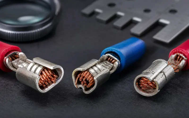
Pull-force testing and cross-section analysis together provide the most reliable evaluation of crimp quality. Pull testing measures the tensile strength by applying force until the terminal separates from the wire. Cross-section analysis cuts through the crimp to reveal internal structure.
Pull testing serves as the primary method for production validation. The test applies a controlled force at 25 mm per minute until failure occurs. Results must meet minimum requirements based on wire gauge, typically reaching 90% of the wire’s ultimate tensile strength for Class 3 applications.
Cross-section analysis confirms what pull testing cannot see. A microscope examination of the cut crimp reveals strand compression, conductor fill, and metal-to-metal contact. This test identifies insulation in the conductor barrel, cut strands, or incomplete compression.
Crimp height measurement checks process control in real time. Manufacturers measure the compressed barrel height after each crimp using precision gauges. Each terminal and wire combination has a specified range, typically provided by the terminal manufacturer.
Crimp force monitoring tracks the actual pressure applied during every crimp. The system flags deviations immediately, preventing defects before they occur.
Electrical resistance testing checks the quality of metal-to-metal contact. A low-resistance measurement confirms proper conductor compression and gas-tight contact between terminal and wire strands.
Cross-section inspection requires cutting the crimped terminal perpendicular to the wire axis and examining the cut surface under magnification. The sample must be mounted, polished, and sometimes etched to reveal crimp details clearly.
Proper conductor crimp shows compression of all wire strands into a compact mass. The terminal barrel should conform to the conductor shape with no gaps. Individual strands must remain intact without cuts or severe deformation.
The inspection checks for complete strand engagement within the crimp barrel. All conductor strands should appear compressed and in contact with the terminal interior. Missing strands or voids indicate improper wire insertion or insufficient crimp force.
Insulation crimp evaluation confirms the insulation support grips the wire jacket without penetrating the conductor area. The insulation barrel should compress the jacket enough to provide strain relief. No insulation material should intrude into the conductor crimp zone.
Bell-mouthing at the crimp entrance signals insertion problems. The conductor should enter the barrel smoothly without flaring or strand separation.
Strand fractures or severe nicking indicate over-crimping. The terminal barrel should compress strands without cutting them. A properly formed crimp deforms strands into hexagonal shapes while maintaining strand integrity.
The crimp should fill 70-90% of the terminal barrel cross-section. Underfilled barrels indicate under-crimping or wrong terminal selection. Overfilled barrels suggest excessive wire stripping or wrong wire gauge.
IPC/WHMA-A-620 sets acceptance criteria for wire harness crimps across three performance classes. Class 3 applications require pull-off force reaching at least 90% of the wire’s ultimate tensile strength. Class 2 applications accept lower thresholds based on application requirements.
Pull force minimums depend on wire gauge and conductor material. For example, a 20 AWG wire requires about 13 pounds of force before failure, while a 16 AWG wire requires at least 25 pounds.
UL 486A and UL 486B specify requirements for electrical connectors and terminals. These standards define minimum pull force values by wire size and connector type. Testing procedures specify grip placement and pull rate.
MIL-DTL-22520 covers military and aerospace crimping tools and processes. The standard requires Type 1 tool certification with documented pull test results. Acceptance criteria mandate wire break as the preferred failure mode.
SAE AS7928 applies to aerospace wiring systems. The standard specifies pull rates of 25.4 mm per minute and strict tensile requirements. Crimps must meet minimum force thresholds without terminal separation.
Cross-section analysis uses visual criteria from IPC/WHMA-A-620. Acceptable crimps show compressed strands filling the barrel without cuts or severe damage. No insulation should appear in the conductor crimp area.
The standard requires full strand engagement within the crimp barrel. All visible conductor strands must show compression and contact with the terminal. Strand pullout or missing strands are failures.
Crimp height specifications come from terminal manufacturers. Each terminal design has a defined range, typically 0.05-0.15 mm. Measurements outside this range indicate improper crimp force settings.
USCAR-21 applies to automotive electrical connections. The standard combines temperature cycling with pull testing to simulate vehicle conditions. Crimps must withstand thermal stress without loss of pull strength.