CNC Spring Forming: Compression, Extension & Torsion Spring Production Guide
Jump to section
CNC spring forming machines use computer-controlled systems to shape metal wire into compression, extension, and torsion springs with high precision and speed. These machines replace manual methods by automating the coiling, bending, and forming process, which allows manufacturers to produce thousands of identical springs with accuracy down to 0.01mm. The technology works for wire diameters from 0.2mm to 14mm, depending on the machine model and wire hardness.
The three main spring types serve different mechanical functions. Compression springs resist pushing forces, extension springs resist pulling forces, and torsion springs resist twisting forces. Each type requires specific forming techniques and tooling setups on CNC equipment.
This guide explains how CNC machines produce each spring type, what makes them different from each other, and which forming method works best for specific applications. Readers will learn the technical differences between coiling machines and multi-axis formers, plus how to select the right spring type for their project.
CNC spring forming uses computer-controlled machines to bend wire into precise spring shapes with tolerances as tight as ±0.01mm. These machines handle wire diameters from 0.2mm to over 4mm and work with steel, stainless steel, copper, and specialty alloys.
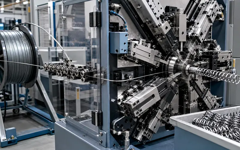
CNC spring forming machines feed wire through multiple axes that bend and coil it around mandrels. The process starts when wire feeds into the machine at a controlled speed. A computer program directs 3 to 8 tooling slides to position themselves around the wire path.
The machine’s axes work together to create the spring’s geometry. One axis controls wire feeding. Another rotates the mandrel that determines coil diameter. Additional axes position bending tools to create hooks, loops, or leg angles for torsion springs.
Real-time sensors monitor wire position and tension throughout forming. The machine adjusts motor speeds to prevent wire deformation or breaks. After the final coil forms, an automated cutter separates the spring from the wire feed.
The entire cycle takes seconds per spring. The machine stores programs for different spring designs, so operators switch between compression, extension, and torsion springs by loading a new file.
CNC spring forming machines process wire diameters between 0.2mm and 4mm. Basic 3-axis machines handle 0.2mm to 2mm wire. Heavy-duty models work with 1.2mm to 4mm diameters for industrial springs.
The machines form multiple materials without tool changes. Steel wire accounts for most production. Stainless steel resists corrosion in medical and food applications. Copper and brass work for electrical components. Specialty alloys like Inconel serve aerospace and high-temperature environments.
Modern CNC systems achieve ±0.2mm tolerance on standard production runs. High-precision models reach ±0.01mm for medical devices and electronics. The tolerance applies to coil diameter, pitch spacing, and overall spring length.
Common Wire Materials:
Material hardness affects forming speed but not accuracy. Softer materials like copper allow faster production cycles. Harder alloys require slower feed rates to prevent tool wear.
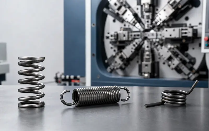
Each spring type serves a distinct mechanical function based on how the wire is wound and how the spring stores energy. Compression springs push back when squeezed, extension springs pull back when stretched, and torsion springs rotate when twisted.
Compression springs resist compressive forces by pushing back when compressed. The wire coils around a mandrel in a helical pattern with space between each coil. This spacing allows the spring to compress without coils touching until maximum load is reached.
CNC coiling machines control the pitch during formation. The pitch is the distance between each coil. Operators set the wire diameter, coil diameter, and number of coils based on the required load capacity.
The ends require grinding flat in most applications. Flat ends distribute force evenly and prevent the spring from tipping during compression. The grinding process removes material until both ends sit perpendicular to the spring axis.
Key specifications include:
Extension springs resist pulling forces by storing energy when stretched. The coils wind tightly together with no space between them in the relaxed state. This tight winding creates initial tension that must be overcome before the spring extends.
The wire forms hooks or loops at each end during the coiling process. These end configurations attach the spring to other components. Common end types include machine hooks, crossover loops, and side hooks. The CNC machine bends the wire into these shapes immediately after coiling the body.
Initial tension varies based on coiling speed and wire properties. Tighter coiling creates higher initial tension. This tension determines how much force is needed before the spring begins to extend.
The spring rate remains constant once extension begins. Extension springs often appear in garage doors, trampolines, and automotive assemblies where pulling force is required.
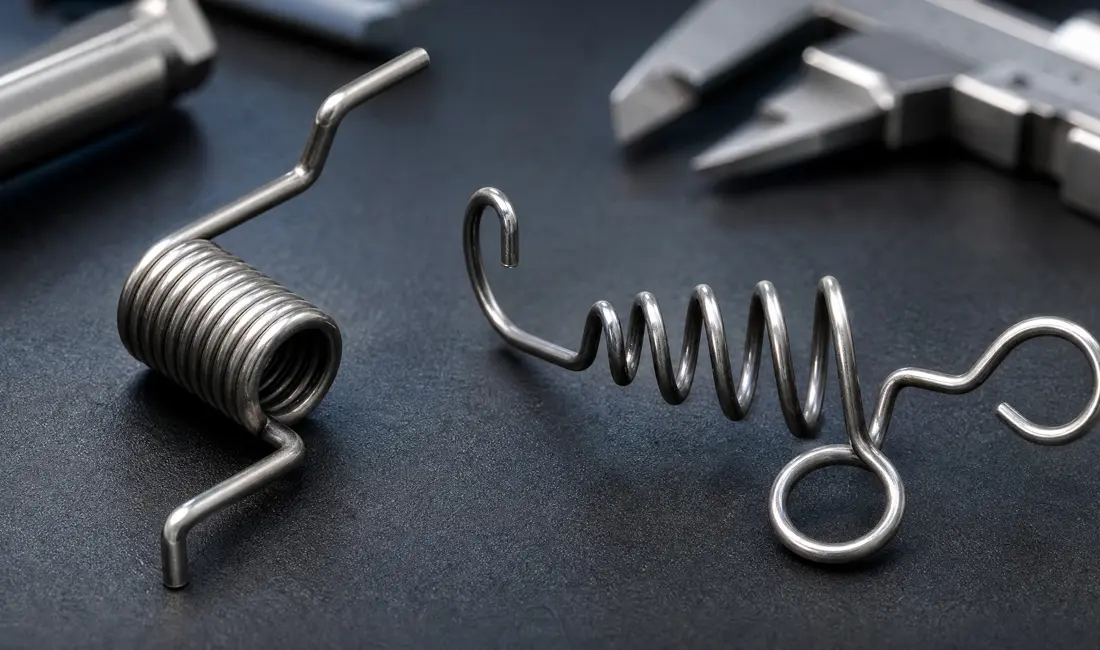
Torsion springs exert rotational force when twisted around their axis. The wire winds into a helical coil, but the spring stores energy through twisting rather than compression or extension. Each end extends outward as a leg or arm that transfers torque.
CNC machines position these legs at precise angles during formation. The angle between legs determines how the spring mounts and where it applies force. Leg length and bend radius affect the torque characteristics.
The coils sit close together but do not touch in the neutral position. When torque is applied, the spring winds tighter or unwinds depending on the direction of rotation. The spring attempts to return to its original position.
Torsion springs differ from other types through:
The wire diameter and number of active coils determine the spring rate for torsion applications. Larger diameter wire provides more resistance to twisting.
Each spring type handles force differently and fits specific mechanical needs. Compression springs resist pushing forces, extension springs resist pulling forces, and torsion springs resist twisting forces.
Compression springs store energy when pushed together along their axis. The coils compress closer together under load. They return to their original length when the load releases.
Extension springs store energy when pulled apart along their axis. The coils separate from each other under tension. Most extension springs include initial tension, which is a preload that must be overcome before the spring begins to stretch.
Torsion springs store energy through rotational force around their axis. The spring winds tighter or looser as torque applies. The legs on each end of the spring transmit the rotational force to the attached components.
Compression springs offer high load capacity and long service life. They work well in applications with limited radial space but adequate axial space. The main disadvantage is buckling risk in applications with high deflection ratios or insufficient lateral support.
Extension springs provide compact designs and easy installation in tension applications. They handle pulling forces efficiently. The disadvantages include stress concentration at the hooks or loops, which can reduce fatigue life. The initial tension can vary between springs in the same batch.
Torsion springs deliver precise torque control and excellent rotational performance. They maintain consistent force through their working range. The disadvantages include requiring careful mounting to prevent side loading. They also need adequate space for the spring body to rotate without interference.
Choose compression springs for applications requiring resistance to pushing forces. These include vehicle suspension systems, valve assemblies, and mechanical cushioning devices. They work best when the spring operates in a hole or over a rod for guidance.
Choose extension springs for applications requiring resistance to pulling forces. These include garage door counterbalances, trampolines, and spring-loaded hinges. Extension springs suit applications where the spring must return components to their resting position after extension.
Choose torsion springs for applications requiring rotational force or torque. These include clothespins, door hinges, clipboards, and rocker switches. Torsion springs fit applications where components rotate around a fixed axis rather than move linearly.
Spring coilers handle high-volume production of standard compression and extension springs, while multi-axis formers create complex geometries including torsion springs and wire forms. The choice depends on spring design complexity, production volume, and required tooling flexibility.
A spring coiler feeds wire through a coiling point and wraps it around a mandrel to create helical coils. The machine controls wire diameter, coil diameter, pitch, and free length through two to four tool slides. Coilers produce compression springs and extension springs efficiently at high speeds.
A multi-axis spring former uses six to eight independent tool slides positioned around the wire feed point. Each slide can bend, form, and position wire in multiple directions during a single production cycle. This design allows the machine to create torsion spring legs, hooks, loops, and complex wire forms that require bends beyond simple helical coiling.
The coiler excels at repetitive cylindrical spring production. The former handles designs that need wire manipulation in multiple planes. Coilers typically run faster for standard spring types. Formers accommodate nearly any bendable wire configuration but operate at slower cycle times.
Spring Coiler Advantages:
Spring Coiler Disadvantages:
Multi-Axis Former Advantages:
Multi-Axis Former Disadvantages:
Choose a coiler when producing compression or extension springs with standard end types in volumes above 10,000 pieces. The machine delivers lower unit costs and faster delivery for these applications. Coilers work best for springs with consistent pitch, cylindrical bodies, and closed or open ends.
Choose a multi-axis former when the spring design includes torsion legs, complex hooks, variable pitch, or requires multiple bends. Formers handle prototype runs and production volumes below 10,000 pieces more economically than coilers due to faster setup. Medical device springs, custom wire forms, and aerospace springs with tight tolerances benefit from multi-axis control.
Wire diameter also determines machine selection. Coilers handle specific diameter ranges and require different models for thin wire versus heavy wire. Multi-axis formers accommodate broader diameter ranges on a single machine, reducing equipment investment for manufacturers producing varied spring sizes.
Compression spring manufacturing begins with material selection and wire preparation. The wire is straightened, cleaned, and measured to ensure a consistent diameter before coiling.
CNC coiling machines wind the wire around a mandrel to create uniform coils with precise pitch and diameter. The machines use programmed parameters to control coil spacing and diameter.
Heat treatment follows coiling to relieve internal stress. Springs are placed in temperature-controlled ovens to restore the wire’s ductility and strength.
End grinding produces flat, parallel surfaces on both ends of the spring, allowing it to sit squarely and distribute loads evenly.
Shot-peening strengthens the spring surface by introducing compressive stress, which extends fatigue life.
Surface finishing protects against corrosion and improves appearance. Common finishes include zinc plating, powder coating, black oxide, or passivation for stainless steel springs.
Final inspection verifies dimensional accuracy and load performance. Technicians measure wire diameter, coil diameter, free length, and spring rate to confirm the part meets specifications.
CNC spring coiling machines achieve tolerances of ±0.01mm compared to ±0.1mm or greater with manual machines. Computer-controlled servo motors adjust wire feed, coiling speed, and pitch in real time to maintain consistency.
Production speed increases by 300% to 500% with CNC equipment. A CNC machine produces 60 to 100 springs per minute depending on complexity, while manual machines produce 15 to 20 springs per minute.
CNC machines eliminate operator variation between parts. Manual coiling requires constant adjustment, which introduces inconsistencies in coil diameter, pitch, and length.
Setup time decreases from hours to minutes with CNC systems. Operators load digital tool paths and material specifications instead of manually calibrating mechanical stops and guides.
Complex spring geometries require CNC control for repeatable accuracy. Torsion springs with custom leg angles and extension springs with formed hooks cannot be reliably produced at tight tolerances using manual equipment.
High-carbon steel (ASTM A228) is the standard material for general-purpose springs. This music wire provides tensile strengths from 230,000 to 400,000 psi and is suitable for most commercial applications at temperatures below 250°F.
Stainless steel (302, 304, 316) provides corrosion resistance for medical, food processing, and marine environments. Type 316 offers the highest corrosion resistance. Stainless steel springs operate at lower stress levels than high-carbon steel.
Chrome-silicon alloy (ASTM A401) is used for high-stress applications and elevated temperatures up to 475°F. It is common in automotive valve springs and industrial equipment exposed to shock loading.
Chrome-vanadium steel is suited for applications requiring impact resistance and temperatures up to 425°F. This alloy maintains spring properties under repeated dynamic loading.
Phosphor bronze and beryllium copper are used in electrical applications that require conductivity and corrosion resistance. These materials handle lower stress levels but provide stable electrical properties across temperature ranges.
Inconel and other nickel alloys are used for temperatures above 600°F in aerospace and power generation. Although more expensive than high-carbon steel, they maintain spring properties at extreme temperatures.