How to Design an Efficient Dust Collection System: Essential Considerations for Manufacturers
Jump to section
To build a great dust collection system, you need to find where the dust is coming from, figure out how much airflow you need, and choose the right equipment. A bad design wastes money and energy while failing to keep your factory safe.
This guide covers the whole process from start to finish. It teaches you how to locate dust sources, design intake hoods, calculate airflow, and plan efficient ductwork. You will also learn how to choose the right dust collector, select the proper fans, add fire safety features, and lower your overall operating costs.
Every factory is different because different materials create different types of dust. By understanding how your specific dust behaves, how fast the air needs to move, and how air resistance affects your system, you can easily avoid common mistakes and keep your workplace clean and running perfectly.
A dust collection system is an air quality improvement system. It extracts airborne dust from work areas, pulls it through a network of ducts, and filters out the particles.
Every dust collection system relies on three essential parts that work together to remove airborne particles.
The fan creates suction that pulls air and dust away from the emission point. It generates enough force to overcome resistance from ductwork and filters.
The filter captures dust particles while allowing clean air to pass through.
The collection hopper stores captured dust until disposal or recycling. It sits below the filter and uses gravity to collect particles that fall during the cleaning cycle.
Centralized systems add ductwork to connect multiple collection points to a single filter unit. Duct diameter and layout affect air velocity and system efficiency. Proper duct design prevents dust from settling inside pipes and blocking airflow.
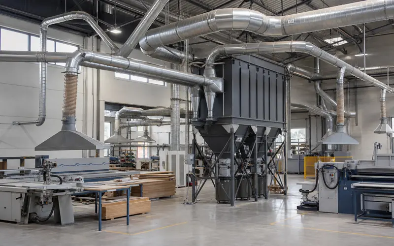
Identifying primary dust sources is the foundation of system design.
Common industrial dust sources include:
A walkthrough of the production floor during normal operations helps spot visible dust clouds. These locations need immediate capture at the source before particles spread throughout the workspace.
The type of material being processed determines dust characteristics. Wood creates larger, lighter particles than metal grinding creates fine, heavy dust. Pharmaceutical powders behave differently than concrete dust.
Some dust sources operate continuously while others run intermittently. A woodworking saw that runs 8 hours daily needs different consideration than a grinder used 30 minutes per shift.
Temperature at the dust source matters. Hot processes require cooling before dust enters collection equipment. Chemical reactions or moisture can make dust sticky and harder to collect.
Mark each identified source on a facility floor plan. This visual reference helps calculate ductwork runs and equipment placement in later design steps.
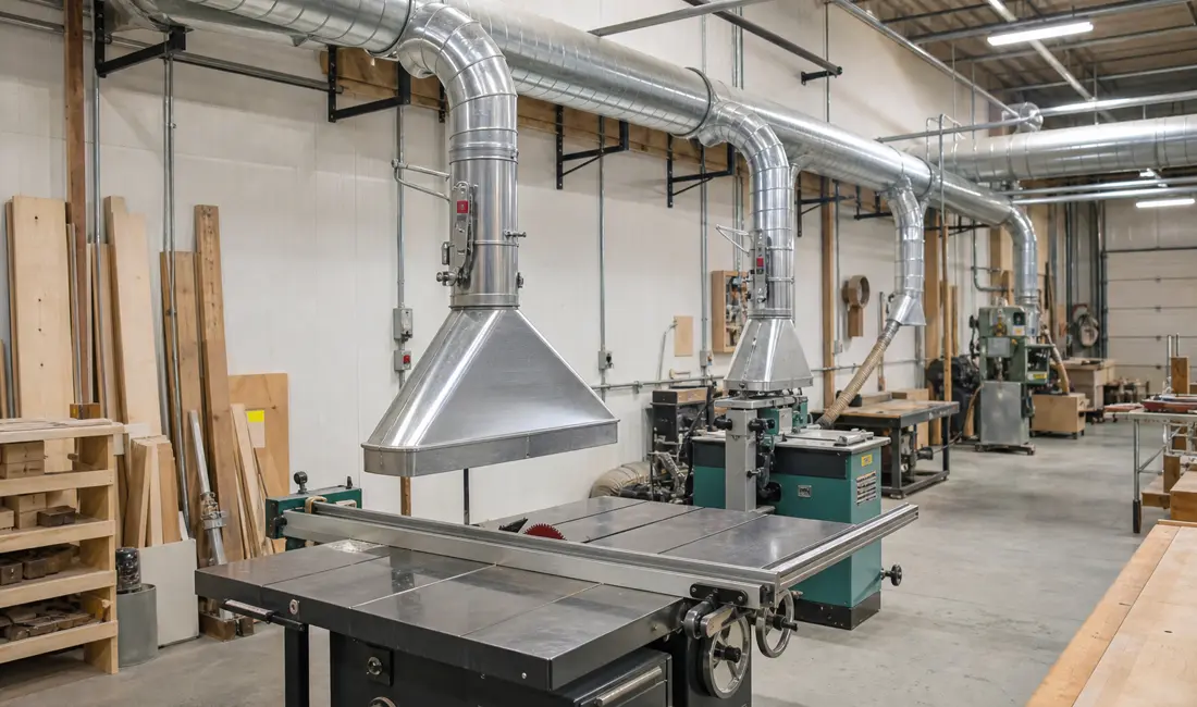
The hood design determines how much dust the system captures and how much energy it uses.
Manufacturers can choose from five external hood types:
Raw edge hoods pull air from both front and back, creating turbulence and wasting energy. Adding a flange focuses airflow to the front zone only. Tapered and conical designs reduce turbulence at the duct entry. Bell mouth hoods combine smooth airflow with focused capture.
Hood Position Matters More Than Hood Type
Position the hood as close as possible to the dust source. Moving a 4-inch hood from 12 inches to 6 inches away from the dust source reduces required airflow from 1,009 cubic feet per minute to 259 cubic feet per minute. This 75% reduction in airflow means smaller ducts, smaller collectors, and smaller fans.
To calculate airflow (CFM), a designer first finds the machine that needs the most air. For example, a large grinder needs up to 2,000 CFM, but a small sander only needs 300 CFM.
Many factories do not run all machines at the same time. In this case, the designer does not add all the CFM numbers together. Instead, the calculation only counts the maximum number of machines running at the exact same time. This ensures the dust collector matches the peak load.
Required CFM by Common Industrial Dust Sources:
| Dust Source | Typical Duct Size | CFM Required |
| Grinding station | 6-8″ | 1,000-2,000 |
| Conveyor transfer point | 6-10″ | 500-1,500 |
| Mixing/blending vessel | 6-8″ | 500-1,000 |
| Sanding/deburring booth | 6-8″ | 500-1,500 |
| Packaging/filling line | 4-6″ | 300-800 |
| Welding fume extraction | 4-6″ | 300-600 |
The collector must deliver this CFM at the pickup point, not at the collector inlet. Static pressure from ductwork reduces delivered airflow. Longer duct runs and additional elbows increase pressure loss and reduce effective airflow at the source.
Adding a 10-20% safety margin to peak airflow requirements accounts for system losses and future production changes.
Main trunk line diameter should match the total airflow requirement. Reducing duct diameter before a pickup point creates bottlenecks that reduce capture performance. Blast gates at each branch connection allow operators to isolate idle equipment and concentrate airflow where it is needed.
A top-down layout drawing of the facility serves as the starting point for ductwork routing. Each machine’s exact location and dust port position should be marked.
Mark these critical details on the layout:
The main duct line should run so it ends directly above each dust port. Keep the path as straight as possible to reduce static pressure loss and maintain airflow efficiency.
Place machines with the highest CFM requirements closest to the dust collector. This reduces the distance dust must travel through the ductwork and minimizes pressure drop across the system.
Ductwork routing should avoid these obstacles:
Blast gates at each branch connection let operators isolate machines not in use. This prevents wasted airflow to idle equipment.
Branches at 30-degree angles work best when connecting machines to the main trunk line. This angle maintains proper air velocity and prevents dust from settling in the ductwork.
At least 3 feet of clearance below ductwork is recommended for safe passage and maintenance access. This spacing prevents head injuries and allows for future adjustments to the layout.
The dust collector type depends on particle size, dust load, and material properties. Three main types handle different conditions.
Baghouse Collectors work well for particles in the 1-10 micron range and above. They use fabric filter bags to trap dust as air passes through. These collectors achieve 99% or higher efficiency for particles above 1 micron. Sub-micron particles may require additional filtration stages.
Cyclone Collectors remove larger particles using centrifugal force. Standard cyclones are most effective above 10 microns, while high-efficiency designs can capture particles down to 5 microns. They cost less than baghouses but are not suitable for fine dust on their own.
Cartridge Collectors fit compact spaces and handle moderate dust loads. They use pleated filter cartridges instead of bags. Cartridges provide more surface area per square foot than bags.
Filter media selection matters as much as collector type. Standard polyester handles most general applications. Temperature-resistant materials like aramid or fiberglass work for hot processes above 200°F. Static-dissipative fabrics prevent sparks in combustible dust environments.
| Collector Type | Best For | Efficiency | Maintenance |
| Baghouse | Particles above 1 micron | 99%+ | Medium |
| Cyclone | Coarse particles | 80-90% | Low |
| Cartridge | Medium dust loads | 95-99% | High |
Manufacturers should size the collector based on airflow requirements from previous calculations. Adding 20% capacity allows for future expansion or variations in production. The fan must generate enough static pressure to overcome system resistance while maintaining required airflow.
Combustible dust requires explosion-rated collectors with safety features. These include spark detection, explosion vents, and flame arrestors. NFPA standards mandate specific protections based on dust properties.
The fan must operate where the fan curve intersects the system resistance curve. This point determines the actual airflow and pressure the system delivers.
Calculate Total System Resistance First
Add up all pressure drops in the system, including ductwork losses, elbows, entry points, filters, and the dust collector. Total static pressure requirements in most dust collection systems range from 4 to 10 inches of water gauge.
Plot the Operating Point
Place the required airflow on the horizontal axis and total static pressure on the vertical axis. The intersection shows where the system operates. The selected fan must pass through this point within its performance range.
Stay Within Peak Efficiency Zone
Fans deliver peak efficiency in a specific range, usually 60 to 80 percent of maximum capacity. Operating outside this zone wastes energy and increases costs.
Account for Filter Loading
Filters accumulate dust and increase resistance over time. Add 1 to 2 inches of water gauge to account for filter loading between cleanings. The fan must maintain required airflow even as resistance increases.
Avoid These Common Errors
AMCA-certified fan curves from the fan manufacturer help verify real-world performance. Brake horsepower requirements should match available motor sizes. A variable frequency drive allows fan speed adjustment as system resistance changes over time.
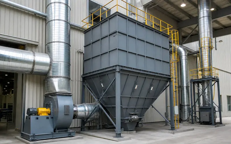
Dust collectors require protection against fires and explosions because combustible dust particles create serious hazards when dispersed in air.
Prevention measures reduce ignition risk before explosions start:
Protection systems limit damage using active or passive methods. Passive systems use vent panels to safely release pressure and flames, or flameless venting with filters for indoor areas. Active systems use sensors to detect sparks or pressure, triggering suppression powder to extinguish flames early. Isolation devices—like valves on air inlets and standardized rotary valves on hoppers—prevent explosions from spreading to connected equipment.
Energy-efficient systems cut operating costs by 20–40% through smart equipment choices, optimization, and maintenance:
What Is the Difference Between a Centralized and a Decentralized Dust Collection System?
A centralized system uses one large collector connected to multiple machines through ductwork. It costs less to maintain but requires careful airflow balancing.
A decentralized system uses separate, smaller collectors at each machine. It is better suited for scattered layouts or incompatible dust types, though it increases the number of filters to service.
How Often Should Dust Collection Filters Be Replaced?
Filters should be replaced when the differential pressure exceeds the manufacturer’s recommended limit, typically 4 to 6 inches of water column. Depending on dust load and production volume, replacement intervals range from 6 months to 2 years.
Can a Dust Collection System Be Added to an Existing Production Line?
Yes, a facility can add a system later. The designer must map the current layout, fit custom hoods around workflows, and route pipes around obstacles. The factory must also have enough electrical power for the new motor and add explosion protection for combustible dust.