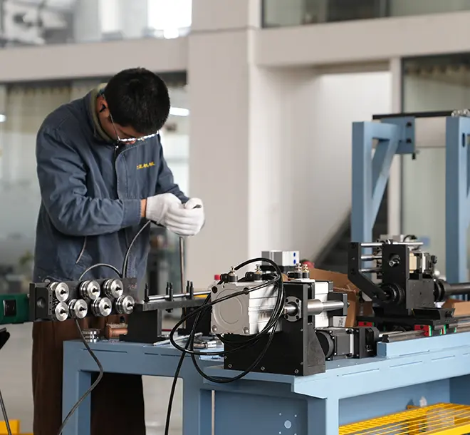
Fan Flange Types & Forming Equipment for HVAC Workshops
Jump to section
HVAC workshops produce three flange types: axial fan housing, TDC, and TDF. They also form axial fan front discs as related components. Each part calls for different forming equipment. Five machine categories cover this work: spinning, horizontal flanging, hydraulic vertical flanging, corner punching, and roll forming. The right machine depends on flange type, workpiece size, sheet thickness, output target, and SMACNA standard. This article maps the flange types, the forming equipment, the trade-offs between methods, and the selection criteria for HVAC duct workshops.
A fan flange is a metal rim that joins fan housings, axial fan casings, or rectangular duct sections in HVAC systems. It seals the airflow path and distributes mechanical load across joints. It also keeps ducts and fans stable in service.
A fan flange is a metal connector that bolts, rivets, or clips a fan or duct to adjacent parts.
The flange has three jobs in an HVAC system. It seals pressurized airflow against leakage. It carries load across the joint so the duct does not deform under static pressure. It also gives the assembly team a clean, repeatable connection point during installation.
Modern HVAC workshops use mechanized forming instead of cutting and welding angle steel by hand. Mechanization standardizes joint geometry, removes weld distortion, and reduces operator skill dependency.
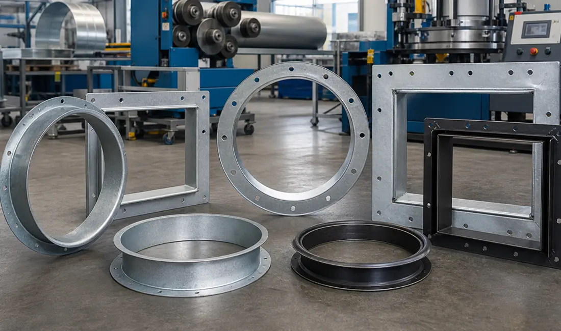
HVAC workshops produce four fan flange variants. Axial fan housing flanges ring the fan casing. TDC duct flanges have an outward hem. TDF duct flanges have an inward hem. Axial fan front discs form the structural front face of axial fan units.
An axial fan housing flange is a circular metal rim that wraps the open end of an axial fan casing.
Industrial axial fans, roof exhaust units, and tunnel ventilation fans use these flanges. The flange forms directly on the cylindrical casing through horizontal rolling or vertical hydraulic flanging.
A TDC duct flange is a roll-formed flange profile that runs along the four edges of a rectangular duct.
The TDC profile is rolled directly from the duct sheet. The hem turns outward, and SMACNA classifies it as T-25a. Four corner pieces lock the sides into a rigid frame at each duct end. Two duct sections then bolt together through the corners.
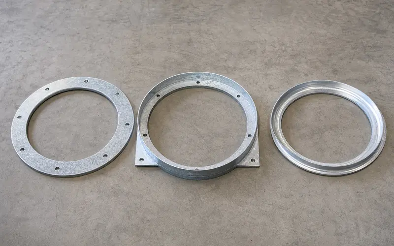
A TDF duct flange is a roll-formed flange profile with the metal hem folded inward.
TDF and TDC share construction and installation methods. The hem direction is the main visible difference. TDF leaves a folded edge on the outer face. SMACNA classifies TDF as T-25b. The folded outer edge is safer to handle on the job site.
An axial fan front disc is a spun metal panel that forms the front face of an axial fan unit.
The front disc is part of the flanged subassembly, not a flange itself. Metal spinning shapes it from a flat blank. It mates with the housing flange during fan assembly.
Axial fan flanges are circular rims formed around fan casings. TDC and TDF duct flanges are straight roll-formed profiles running along rectangular duct edges. The three differ in geometry, hem direction, forming method, joining hardware, and workshop position.
The table compares the three flange types across structural and process attributes.
| Attribute | Axial Fan Flange | TDC Duct Flange | TDF Duct Flange |
| Geometry | Circular ring | Straight + corner pieces | Straight + corner pieces |
| Hem direction | Not applicable | Outward | Inward |
| SMACNA reference | Not applicable | T-25a | T-25b |
| Workpiece form | Cylindrical casing | Rectangular duct from coil | Rectangular duct from coil |
| Joining hardware | Bolts and gasket | Corners, bolts, clips | Corners, bolts, clips |
| Forming method | Spinning, rolling, hydraulic flanging | Roll forming + corner punching | Roll forming + corner punching |
| Workshop position | Fan assembly cell | Rectangular duct main line | Rectangular duct main line |
Axial fan flanges fit three scenarios. The workpiece is a circular fan casing or front disc. The joint must carry radial pressure and vibration. The workshop produces fans rather than duct sections.
TDC suits rectangular duct workshops that need a strong, repairable connection. The outward hem creates a sharper edge on the duct’s outside surface.
TDF suits workshops that move ducts by hand. The inward hem keeps the outer surface safe to handle and clean.
Five categories cover HVAC fan flange production: spinning machines, horizontal flange formers, hydraulic vertical flangers, TDC corner punchers, and TDC roll formers. Each handles a specific flange geometry.
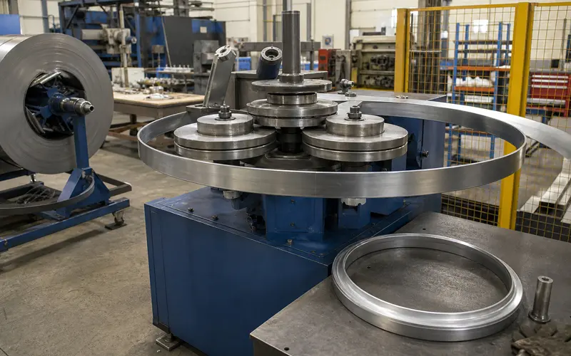
An axial fan front disc spinning machine is equipment that rotates a flat blank against shaping rollers.
It suits front discs, inlet cones, and bell mouths. The same equipment supports a wide range of blank diameters and sheet thicknesses.
A horizontal axial fan flange forming machine is equipment that uses rollers to form the casing rim horizontally.
The BOHC-1250 model handles fan casings from 300 to 1250 mm in diameter. It works with sheet thickness from 1.5 to 4 mm. The horizontal bed prevents gravity-driven distortion on large-diameter parts.
A hydraulic vertical fan flanging machine is equipment that flanges the casing rim using hydraulic pressure on a vertical axis.
The vertical setup loads the casing upright with an overhead hoist. The BOHD-1250 has the hydraulic force to flange thicker or harder stock in a stable, repeatable cycle.
A TDC duct corner punching line is equipment that punches and forms the L-shaped corner pieces for TDC flange assemblies.
This line supplies the rectangular duct main line with corner inserts matching SMACNA T-25a geometry. It runs continuously and matches the duct main line cycle time.
A high-speed TDC flange roll former is equipment that pulls steel coil through rollers to produce the TDC flange profile.
Line speed, coil width range, and profile change-over time are the three key throughput numbers operators watch.
Horizontal fan flange forming clamps the fan casing on a horizontal axis and rolls the rim progressively. Vertical hydraulic flanging holds the casing upright and forms the rim through one hydraulic stroke. They differ in setup, force pattern, and workpiece envelope.
Both BOHC-1250 and BOHD-1250 form the same flange feature using different mechanics. The horizontal model rolls the rim progressively. Forming stress spreads over the rotation cycle, which protects thin walls from buckling. The vertical model uses hydraulic pressure for one controlled stroke. That stroke flanges thicker or harder material with shorter cycle time. Loading style also differs. Horizontal beds support the casing along its length. Vertical fixtures need lift-and-place loading.
The horizontal model fits workshops with thin-wall, large-diameter casings. Progressive forming improves dimensional consistency on these parts.
The vertical model fits workshops with thicker or harder stock. It also fits short cycle time targets and vertical headroom in the work cell.
Spinning, roll forming, hydraulic flanging, and corner punching each suit a different fan flange type. Their advantages cover surface quality, throughput, and material range. Disadvantages cover tooling cost, change-over time, and workpiece size limits.
Spinning forming for front discs delivers smooth curved surfaces with high material yield. The trade-off is a slower cycle and more dependence on operator technique.
Horizontal roller flange forming creates uniform rims with low forming stress. This makes it the safer choice for thin-wall, large-diameter casings. Single-piece time exceeds a stroke press, and the machine takes lateral floor space.
Hydraulic vertical flanging brings high forming force and a stable single-stroke cycle. It suits thicker stock. Tooling investment is higher, and different casing diameters need different dies.
TDC roll forming with corner punching gives continuous high-speed output. It pairs well with the rectangular duct production line. The system is locked into the TDC profile family. Other duct flange systems require different equipment.
Selecting fan flange forming equipment depends on flange type, workpiece size, material thickness, output, automation level, and floor space. Engineers match these attributes against each machine category before committing to a configuration.
The list below shows the main decision factors before issuing an equipment specification.
Once these attributes are listed, the right machine becomes clear. Curved front discs call for a spinning machine. Thin-wall, large-diameter casings call for the horizontal flange former. Thick or hard stock with tight cycle times calls for the hydraulic vertical flanging machine. A TDC-based rectangular duct line needs the corner punching line and the high-speed TDC roll former together.
HVAC fan flange production follows SMACNA HVAC Duct Construction Standards. TDC profiles map to T-25a, and TDF profiles map to T-25b. Both serve medium and high-pressure rectangular duct systems. SMACNA grades the TDC family as T-20, T-25, T-30, T-35, and T-40. Stiffness and sealing capability rise as the rated pressure increases. Aligning with these standards supports cross-border project documentation and vendor compatibility.
Galvanized steel is the standard material for general HVAC duct. Stainless steel 304 serves corrosion-prone environments such as commercial kitchens and cleanrooms. Aluminum applies where weight matters. Sheet thickness runs 0.5 to 1.5 mm for TDC and TDF coil stock. Axial fan housings use 1.5 to 4 mm sheet, with heavy-duty configurations reaching 5 mm.
The traditional angle steel route required cutting bar stock, drilling bolt holes, welding corners, grinding welds, and applying coatings. Each step added time, scrap, and a chance for joint distortion. Mechanized forming compresses those steps into one machine cycle. Roll formers turn coil into finished flange in one pass. Corner punching lines feed inserts that snap into place. The result is steady output, predictable quality, and less dependence on welding labor.
Fan flange forming sits between upstream coil decoiling, leveling, and cutting and downstream beading, locking, seaming, and packing. Three integration modes exist. Standalone units suit small workshops and pilot lines. Linked work cells suit medium plants. Fully integrated turnkey lines suit OEM contracts with long-shift output requirements. The same equipment also supports industrial ventilation, exhaust fan production, commercial kitchen equipment, and cleanroom ventilation.