Automotive exhaust systems need complex tube shapes. Older bending methods cannot make these shapes. Manufacturers use 3D tube bending instead. It routes pipes around engines, transmissions, and chassis parts. CNC-controlled equipment bends the tubing in multiple planes without welding separate pieces. This cuts leak points and keeps exhaust flow steady.
Manufacturers need to know how each bending method works. They also need to know which method suits their production volume and part complexity. The wrong equipment choice leads to collapsed tubes, wrinkled bends, and scrapped parts.
This guide explains how 3D tube bending is used in exhaust production. It compares the main bending methods. It also covers the equipment specs that decide whether a machine meets production needs.
What Is 3D Tube Bending in Automotive Exhaust Manufacturing?
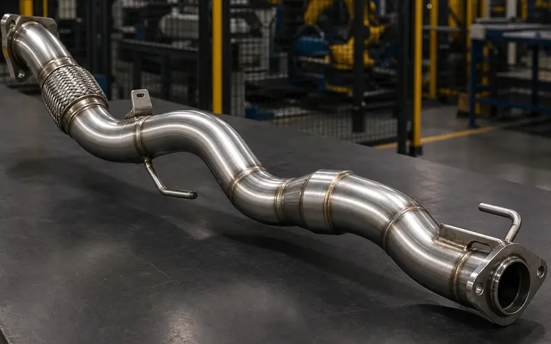
3D tube bending is a CNC-controlled forming process. It creates exhaust parts with curves in multiple planes. This lets pipes route around engine components, suspension parts, and body structures. Exhaust systems need bends in X, Y, and Z axes. This helps them fit tight underbody space while keeping proper flow.
Why Do Exhaust Systems Require Three-Dimensional Bends Instead of Simple 2D Bends?
Exhaust systems must navigate around transmission housings, driveshafts, fuel tanks, and chassis parts. 2D bends only curve in one plane. So the tube needs extra straight sections and welds to change direction. Each extra weld is a place where leaks can start.
3D bends cut 50-70% of weld joints compared to 2D bends and straight connectors. Fewer welds mean fewer leak points. 3D bends also improve exhaust flow by removing sharp transitions that cause turbulence. A single 3D bent tube can follow the shape of the vehicle floor, suspension mounts, and powertrain in one piece.
What Bend Radius and Angle Tolerances Matter for Exhaust Tubing?
Exhaust tube bending without internal support needs a minimum radius of 3 times the outer diameter. This prevents wall thinning and tube collapse. Mandrel or pneumatic support, covered later in this guide, can bend tighter than this.
Critical tolerance specs for automotive exhaust:
- Bend radius: 3-5x outer diameter for unsupported bends (tighter with mandrel or pneumatic support)
- Angle accuracy: ±0.5 degrees, so the exhaust aligns with engine flanges and converter inlets
- Position accuracy: ±2mm, for mounting bracket alignment
- Wall thickness change: under 10% at the bend apex
These tolerances keep the parts fitting together. They also help the tube hold up under heat cycling between 20°C and 800°C.
Which Tube Materials Are Commonly Bent for Automotive Exhaust Production?
Aluminized steel is the most common exhaust material. It has a 409-grade stainless core with an aluminum-silicon coating. It costs 30-40% less than pure stainless steel.
304 stainless steel suits premium and performance exhaust. It resists salt corrosion better than aluminized steel. 321 stainless steel adds titanium stabilization for hot sections near turbochargers and catalytic converters.
| Material | Wall Thickness | Typical Service Life | Typical Cost |
| Aluminized 409 | 1.2-2.0mm | 5-8 years | Baseline |
| 304 Stainless | 1.0-1.5mm | 10-15 years | +40% |
| 321 Stainless | 1.0-1.5mm | 15+ years | +60% |
Exhaust tube diameters run from about 38mm for small engines to 76mm or more for V8s. Standard pneumatic CNC benders typically handle the smaller end of that range.
How Does the 3D Tube Bending Process Work for Exhaust Pipes?
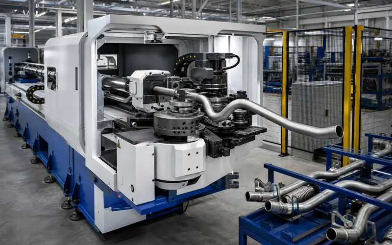
3D tube bending uses computer-controlled machines to shape straight tubing into complex curves. Internal mandrels prevent wall collapse during the bend. Multi-axis controls position the tube through each bend step. Quality checks then confirm the part matches spec.
What Role Does Internal Mandrel Support Play in Preventing Wrinkles and Collapse?
Internal mandrels support the tube wall from inside during bending. This stops wrinkling and collapse on the inner radius. Without this support, compression pushes the wall inward and causes folds on tight-radius bends.
Exhaust pipe bending uses two main mandrel types. Ball mandrels use linked spheres that flex through multiple bends. Segmented mandrels use separate pieces that slide past each other for longer bend sequences. Either way, the mandrel sits just behind the bend point to support the tube and keep it round.
Wrinkled or collapsed sections restrict exhaust flow and cut engine performance. Mandrel bending keeps a steady internal diameter through each curve, which keeps exhaust velocity high and backpressure low.
How Do CNC Multi-Axis Controls Achieve Complex Serpentine Exhaust Shapes?
CNC multi-axis controls rotate, push, and position the tubing through multiple planes. This creates serpentine shapes without straight sections between bends. Older benders need straight tube between each curve, but 3D systems bend continuously. The machine rotates the tube around its centerline while the bending head moves through the programmed angle. This lets the machine bend in different planes without repositioning the tube.
CNC programs store the sequence of rotations, bend angles, and feed distances for each design. The machine then repeats this sequence to produce identical parts across a run. Three-axis machines control tube rotation, carriage feed, and bend die rotation. Five-axis machines add two more rotation axes for complex shapes. BOBO’s CNC pneumatic 3D tube bender runs three servo-driven axes for feeding, rounding, and bending. It also stores up to 900 bending programs for fast recall on repeat runs.
What Quality Checks Confirm Dimensional Accuracy After Each Bend?
Quality checks measure bend angle, centerline radius, and overall length against the design spec. Coordinate measuring machines probe key points along the tube to confirm the shape matches the CAD model.
Common exhaust pipe measurements:
- Bend angle and centerline radius: checked with digital protractors or CMM probes
- Overall length: checked end-to-end against mounting points
- Ovality: checked at bend points to confirm the tube stays round
Visual inspection catches surface flaws like wrinkling, scoring, or excess thinning. Parts beyond the set limits get rejected, since deep flaws restrict flow and weaken the tube. Gauge fixtures confirm the bent pipe lines up with hangers, flanges, and converter inlets.
What Types of 3D Tube Bending Methods Are Used for Exhaust Production, and How Do They Differ?
Automotive exhaust manufacturers use two main 3D bending methods. These are CNC mandrel bending and pneumatic CNC 3D bending. They differ in tooling, precision, speed, and cost.
What Distinguishes CNC Mandrel Bending From Pneumatic CNC 3D Bending?
CNC mandrel bending inserts a solid support rod inside the tube during the bend. This mandrel stops the tube walls from collapsing or wrinkling on tight radii, while the tube rotates around a fixed die.
Pneumatic CNC 3D bending uses compressed air instead of a physical mandrel. The system injects pressurized air into the sealed tube to support the walls from inside. A CNC-controlled bending head then moves the tube through multiple planes. BOBO’s CNC pneumatic 3D tube bender applies this method to automotive exhaust, fuel line, and brake line bending. Its maximum bending angle of 190° supports the tight return bends common in exhaust assemblies.
The mandrel method needs specific tooling for each tube diameter and bend radius. Pneumatic systems skip these tooling changes. Both methods use CNC programming to control bend angles, rotation, and position.
Advantages and Disadvantages of Each Bending Method
| Feature | CNC Mandrel Bending | Pneumatic CNC 3D Bending |
| Wall thickness consistency | Keeps uniform walls on tight bends | Can thin walls on sharp radii |
| Setup time | 15-30 minutes per tooling change | 5-10 minutes between tube sizes |
| Minimum bend radius | 1.5x tube diameter | 2x tube diameter (typical) |
| Production speed | 45-60 bends per hour | 60-90 bends per hour |
| Material waste | 2-3% scrap rate | 3-5% scrap rate |
CNC mandrel bending makes tighter bends without deforming thin-walled stainless tubing. Pneumatic bending skips mandrel wear, cuts tooling costs, and switches between tube sizes faster.
Choose Mandrel Bending or Pneumatic 3D Bending Based on Part Size and Volume
Tight packaging constraints push manufacturers toward CNC mandrel bending. Performance manifolds and headers often use 1.5-2 inch tubing with bend radii under 3 inches, where mandrel support avoids flow restrictions.
High-volume lines with smaller exhaust tubing benefit from pneumatic 3D bending instead, since these systems switch between tube sizes faster than mandrel setups. Truck and heavy-equipment exhaust systems use larger tubes, which typically need mandrel-based or heavier-duty equipment.
Material specs matter too. Thin-wall tubing under 0.065 inches needs mandrel support to avoid collapse. Thicker-wall tubes at 0.083 inches and up can bend with pneumatic pressure alone.
What Equipment Features Should Manufacturers Evaluate When Selecting a 3D Tube Bender for Exhaust Production?
Manufacturers should check tube diameter, die-change speed, and automation level. These factors shape throughput, quality, and running costs.
Match Tube Diameter and Bending Length to the Part Design
Standard pneumatic CNC 3D benders typically cover tube diameters up to about 40mm, or 1.6 inches. This suits smaller exhaust parts like manifolds and headers. Larger vehicles and trucks need mandrel-based or heavier-duty benders sized for bigger tubes.
Bending length sets how much tube the machine can handle in one setup, and longer capacity cuts the need for extra welds. Tight packaging needs machines that can bend down to 1.5 times the tube diameter.
Key capacity specs for standard pneumatic CNC 3D benders:
- Tube diameter range: up to about 40mm (varies by model)
- Wall thickness: 0.8mm to 3mm
- Minimum bend radius: typically 2x tube diameter, up to 4x on some models
Speed Up Changeovers With Fast Clamping and Die Systems
Fast clamping cuts the time between bends from 8 seconds to under 3 seconds. This matters most where a machine runs 15 to 30 bends per exhaust system.
Die-change system comparison:
| System Type | Changeover Time | Labor Required | Best For |
| Manual bolt-on | 45-90 minutes | 2 operators | Single-model runs |
| Quick-change cartridge | 10-15 minutes | 1 operator | Mixed production |
| Servo-driven automatic | Under 5 minutes | None | High-mix, high-volume |
Add Automation Features for Multi-Bend, Multi-Model Production
CNC controls with 3D simulation software catch collision errors before the first real bend. Automatic tool positioning adjusts mandrel depth, wiper die angle, and pressure die position from programmed settings, so operators enter dimensions once and the machine sets up on its own. Multi-stack tooling lets a machine store 4 to 8 bend radii on one turret and rotate to the right die automatically.
Integrated measuring systems check bend angles in real time with laser sensors or vision cameras. The machine adjusts later bends to offset material springback. This keeps angle tolerances within ±0.5 degrees across a full production run.
Frequently Asked Questions
Does 3D Tube Bending Eliminate All Welding in an Exhaust System?
No. 3D bending removes the welds needed to join separate sections into one run. The system still needs welds where the tube meets the muffler, catalytic converter, or mounting brackets.
Can the Same Machine Bend Both Aluminized Steel and Stainless Steel Exhaust Tubing?
Most CNC tube benders can process both materials. Stainless steel needs more clamping force and slower feed rates than aluminized steel, since it work-hardens more during the bend.
How Long Do Mandrels Typically Last Before Needing Replacement?
Mandrel wear depends on tube material, bend radius, and production volume, not a fixed lifespan. Operators usually check mandrels for wear on a set schedule instead of a fixed replacement date.
Conclusion
3D tube bending lets exhaust manufacturers route complex shapes in one piece. This cuts welds and leak points. CNC mandrel bending suits tight-radius, thin-wall parts where flow and wall consistency matter most. Pneumatic CNC 3D bending suits high-volume lines with smaller tubing and frequent size changes. BOBO Machine builds CNC pneumatic 3D tube benders for automotive exhaust, fuel line, and brake line production. Contact BOBO Machine to match the right tube bending equipment to a production line.